
User's Manual

ServSwitch Wizard VGA (USB)
724-746-5500 | blackbox.com
Page 12
724-746-5500 | blackbox.com
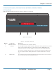
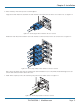
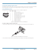
2.6.2 Rear Panel
Figure 2-5 shows the rear panel of the unit. Table 2-4 describes its components:
1
23
4
USB2.0
SWITCHED
USB 1
USB 2
V1
V2
V3
V4
5V
4A
INDOOR
USE
ONLY
USER
CONSOLE
OPTIONS
12 11 11
11 11
4
5 6 7 8 9 8 9 8 9 8 9 10
Figure 2-5. Rear panel.
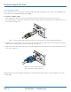
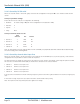
Table 2-4. Rear panel components.
Number Component Description
4 2.5-mm Barrel connector Power input or power supply connects here.
5 (2) USB Type A connectors Connect the console’s USB keyboard and mouse to these connectors.
6 3.5-mm RCA connector User console audio port: Connect optional speakers to this connector.
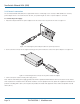
7 RJ-45 port *Options port: This top 10p10c port is used to allow external control of channel
switching and also to update the internal firmware when necessary by connectng to
a computer.
8 (4) USB Type B connectors Connect to a USB port on each computer.
9 (4) 3.5-mm RCA connectors Connect to the speaker output socket on each computer (optional connection).
10 (2) USB Type A connectors Connect to the console's USB 2.0 peripheral devices (optional connection).
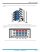
11 (8, 12 or 16) VGA connectors Connect to the video output ports of each computer.
12 (2, 3 or 4) VGA connectors Connect to the console's video monitors to enable multiple video streams from each
computer to be switched to up to four video monitors.
*NOTE: The OPTIONS port uses a 10p10c socket, which can accommodate both 10p10c connectors as well as the much
more common 8p8c connectors, which are used on Ethernet leads and patch cables. The pin-outs for both types of
connectors are listed in Appendix C.