
Specifications


Attenuation
Chapter 3 Optical TAPs
37
rev. 1
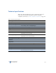
This shows the power loss budget for Link A to the analyzer.
The budget for the analyzer side is 6.751 dB. The network side
allowed us to choose any split ratio, but the analyzer side presents
some limitations. Our budget was 9.0 dB, which is greater than our
6.751 dB availability. Since we only have 6.751 dB available, the split
ratios we can use are 50/50 and 60/40 after looking at Table 5 on
page 33. All others do not provide enough light power to the analyzer.
Link A → Analyzer
Send Device Power -9.000
Receive Device Sensitivity - -17.5
Power Loss Budget 9.000
Number of Connectors 4.0
Connector Loss
1
1. Multimode.
x 0.5
Connector Loss 2.0
Fiber Length Link A (8 meters) 0.008
Fiber Loss Link A
2
2. 850nm multimode.
x 3.0
Fiber Loss Link A total +0.024
Fiber Length to Analyzer (75 meters) 0.075
Fiber Loss Analyzer x 3.0
Fiber Loss Link B total +0.225
Attenuation -2.249
Power Loss Budget - Attenuation
3
3. Light power available for the analyzer. Any split ratio smaller than this number is
feasible so long as the network side is also feasible.
6.751