
Manual


7
3. If the battery pack does not charge properly:
in a lamp or other appliance
to a light switch which turns power off
when you turn out the lights.
c. Move charger and battery pack to
a location where the surrounding air
d. If charging problems persist, take the
tool, battery pack and charger to your local
service center.
4. The battery pack should be recharged when
it fails to produce sufficient power on jobs
which were easily done previously. DO NOT
Follow the charging procedure. You may also
charge a partially used pack whenever you desire
with no adverse affect on the battery pack.
5. Foreign materials of a conductive nature
such as, but not limited to, steel wool, aluminum
foil, or any buildup of metallic particles should
be kept away from charger cavities. Always
unplug the charger from the power supply when
there is no battery pack in the cavity. Unplug
charger before attempting to clean.
6. Do not freeze or immerse charger in water
or any other liquid.
WARNING: Shock hazard. Do not allow
any liquid to get inside charger. Never attempt
to open the battery pack for any reason. If the
plastic housing of the battery pack breaks or
cracks, return to a service center for recycling.
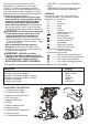
INSTALLING AND REMOVING
THE BATTERY PACK FROM THE
POWER UNIT
is in the center position when installing and
removing batteries.
WARNING: Make certain the lock-off
button is engaged to prevent switch actuation
before removing or installing battery.
: Insert battery
pack into the Power Unit until an audible click
is heard (Figure B). Make sure battery pack is
fully seated and fully latched into position.
epress the
Figure
C and pull battery pack out of the Power Unit.
OPERATING: POWER UNIT
TRIGGER SWITCH & FORWARD/REVERSE
SLIDER
drive screws, reverse to remove screws. It
is located above the variable speed trigger
FIRST, then push the slider to the right hand
side of the tool when viewing from the rear.
After any reversing operations, return lever
to the forward position. Never change the
direction of rotation while the motor is running.
by pulling and releasing the trigger. The
farther the trigger is depressed, the higher
the speed of the Power Unit.
the direction of the tool.
trigger switch and depress the forward/
reverse control button to the left.
reverse control button to the right.
NOTE: When changing the position of
the control button, be sure the trigger is
released.
INSTALLING AND REMOVING ATTACH-
MENTS - FIGURE D
WARNING: Shock hazard. Under no
circumstances should this product be used
near water.
WARNING: Burn hazard. Moving parts
within the Power Unit become hot during use.
Avoid contact with moving parts within Power
Unit when removing and installing accessories.
WARNING: Before assembly, lock the
Power Unit by setting the forward/reverse
the battery from the Power Unit. Remove any
accessory from the attachment before
removing or installing the attachment.
B
C