
Operation Manual

8
ENGLISH
This appliance is not intended for use by per-
sons (including children) with reduced physical,
sensory or mental capabilities, or lack of expe-
rience and knowledge, unless they have been
given supervision or instruction concerning
use of the appliance by a person responsible
for their safety.
Children should be supervised to ensure that
they do not play with the appliance.
Vibration
The declared vibration emission values stated in
the technical data and the declaration of conformity
have been measured in accordance with a standard
test method provided by EN 60745 and may be used
for comparing one tool with another. The declared
vibration emission value may also be used in
a preliminary assessment of exposure.
Warning! The vibration emission value during actual
use of the power tool can differ from the declared
value depending on the ways in which the tool is
used. The vibration level may increase above the
level stated.
When assessing vibration exposure to determine
safety measures required by 2002/44/EC to protect
persons regularly using power tools in employment,
an estimation of vibration exposure should consider,
the actual conditions of use and the way the tool is
used, including taking account of all parts of the
operating cycle such as the times when the tool is
switched off and when it is running idle in addition
to the trigger time.
Labels on tool
The following pictograms are shown on the tool:
Warning! To reduce the risk of injury, the
user must read the instruction manual.
Electrical safety
This tool is double insulated; therefore no
earth wire is required. Always check that the
power supply corresponds to the voltage on
the rating plate.
If the supply cord is damaged, it must be re-
placed by the manufacturer or an authorised
Black & Decker Service Centre in order to avoid
a hazard.
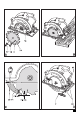
Features
1. On/off switch
2. Lock-off button
3. Main handle
4. Secondary handle
5. Mitre angle scale
6. Locking knob for mitre angle adjustment
7. Parallel fence
8. Shoe
9. Saw blade
10. Saw blade guard
11. Riving knife
12. Depth of cut scale
13. Locking knob for depth of cut adjustment
14. Spanner
15. Saw dust outlet
Assembly
Warning! Before attempting any of the following op-
erations, make sure that the tool is switched off and
unplugged and that the saw blade has stopped.
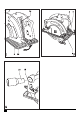
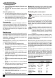
Removing and fi tting a saw blade (fi g. A)
Caution! This method for changing the blade is
only for use with blades that contain a hole (16) for
the purpose of locking the blade whilst fi tting and
removing.
Removing
Insert a screwdriver into the hole (16) to prevent
the saw blade from rotating.
Loosen and remove the blade retaining screw (17)
by turning it counterclockwise using the spanner
(14) supplied.
Remove the outer washer (18).
Remove the saw blade (9).
Fitting
Place the saw blade onto the inner washer (19),
making sure that the arrow on the blade points
in the same direction as the arrow on the tool.
Fit the outer washer (18) on the spindle, with the
raised part pointing away from the saw blade.
Insert the blade retaining screw (17) into the hole.
Insert a screwdriver into the hole (16) to prevent
the saw blade from rotating.
Securely tighten the blade retaining screw by
turning it clockwise using the spanner (14) supplied.
Adjust the riving knife as described below.
Warning! Whenever a new blade is fi tted the saw
blade guard should be checked to ensure that it
can move freely.