
Operation Manual

9
ENGLISH
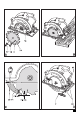
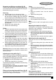
Removing and fi tting a saw blade (fi g. B)
Caution! This method is for changing blades that do
not contain a hole (16) for the purpose of locking the
blade whilst fi tting and removing.
Removing
Set the depth of cut on the saw to 10mm.
Place a plank of wood on the fl oor, then place
the saw onto the leading edge of the wood as
shown in fi g B to prevent the blade from turning.
Whilst applying fi rm pressure on the saw, loosen
and remove the blade retaining screw (17) by
turning it counterclockwise using the spanner
(14) supplied.
Remove the outer washer (18).
Remove the saw blade (9).
Fitting
Place the saw blade onto the inner washer (19),
making sure that the arrow on the blade points
in the same direction as the arrow on the tool.
Fit the outer washer (18) on the spindle, with the
raised part pointing away from the saw blade.
Insert the blade retaining screw (17) into the hole
loosely tighten by hand.
Place a plank of wood on the fl oor, then place
the saw onto the leading edge of the wood as
shown in fi g B to prevent the blade from turning.
Whilst applying fi rm pressure on the saw, se-
curely tighten blade retaining screw (17) by turn-
ing it clockwise using the spanner (14) supplied.
Adjust the riving knife as described below.
Warning! Whenever a new blade is fi tted the saw
blade guard should be checked to ensure that it
can move freely.
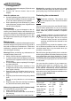
Adjusting the riving knife (fi g. C)
The riving knife prevents the saw blade from jamming
during rip sawing operations. The riving knife must
be adjusted after replacing the saw blade.
Loosen the screw (20) holding the riving knife in
position.
Position the riving knife (11) as shown.
The distance between the toothed rim and the riving
knife should be 2 - 3 mm.
The height difference between the toothed rim and
the lower end of the riving knife should be 2 - 3 mm.
Tighten the screw.
Fitting and removing the parallel fence (fi g. D)
The parallel fence is used to saw in a straight line
parellel to the edge of the workpiece.
Fitting
Loosen the locking knob (21).
Insert the parallel fence (7) through the openings
(22).
Slide the parallel fence into the desired
position.
Tighten the locking knob.
Removing
Loosen the locking knob (21).
Pull the parallel fence off the tool.
Use
This tool can be used in the right hand or the left
hand.
Adjusting the depth of cut (fi g. E)
The depth of cut should be set according to the
thickness of the workpiece. It should exceed the
thickness by approx. 2 mm.
Loosen the knob (13) to unlock the saw shoe.
Move the saw shoe (8) into the desired position.
The corresponding depth of cut can be read from
the scale (12).
Tighten the knob to lock the saw shoe in place.
Adjusting the mitre angle (fi g. F)
This tool can be set to mitre angles between 0°
and 45°.
Loosen the locking knob (6) to unlock the saw
shoe.
Move the saw shoe (8) into the desired position.
The corresponding mitre angle can be read from
the scale (5).
Tighten the locking knob to lock the saw shoe in
place.
Switching on and off
To switch the tool on, move the lock-off button (2)
into the unlock position and squeeze the on/off
switch (1).
To switch the tool off, release the on/off switch.
Sawing
Always hold the tool with both hands.
Let the blade run freely for a few seconds before
starting the cut.
Apply only a gentle pressure to the tool while
performing the cut.
Work with the shoe pressed against the
workpiece.
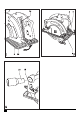
Dust extraction (fi g. G)
An adaptor is required to connect a vacuum cleaner
or dust extractor to the tool. The adaptor can be pur-
chased from your local Black & Decker retailer.