
Quick Start Guide


8
Electrical safety
#
This tool is double insulated; therefore no earth wire
is required. Always check that the power supply
corresponds to the voltage on the rating plate.
u If the supply cord is damaged, it must be replaced by the
manufacturer or an authorised Black & Decker Service
Centre in order to avoid a hazard.
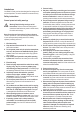
Features
1. On/off switch
2. Lock-off button
3. Main handle
4. Side handle
5. Depth of cut adjustment lever
6. Depth of cut scale
7. Locking knob for mitre angle adjustment
8. Mitre angle scale
9. Saw blade guard
10. Retracting lever for saw blade guard
11. Saw shoe
12. Parallel fence
13. Riving knife
Assembly
Warning! Before attempting any of the following operations,
make sure that the tool is switched off and unplugged and that
the saw blade has stopped.
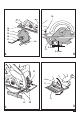
Removing and tting a saw blade (g. A)
Removing
u Insert a screwdriver into the hole (14) to prevent the saw
blade from rotating. Alternatively, hold the outer washer
(15) using an 18 mm spanner.
u Loosen and remove the blade retaining screw (16) by turning
it counterclockwise using the Allen key (17) supplied.
u Remove the outer washer (15).
u Remove the saw blade (18).
Fitting
u Place the saw blade onto the inner washer (19), making
sure that the arrow on the blade points in the same
direction as the arrow on the tool.
u Fit the outer washer (15) on the spindle, with the raised
part pointing away from the saw blade.
u Insert the blade retaining screw (16) into the hole.
u Insert a screwdriver into the hole (14) to prevent the saw
blade from rotating. Alternatively, hold the outer washer (15)
using an 18 mm spanner.
u Securely tighten the blade retaining screw by turning it
clockwise using the Allen key (17) supplied.
u Adjust the riving knife as described below.
Adjusting the riving knife (g. B)
The riving knife prevents the saw blade from jamming during
rip sawing operations. The riving knife must be adjusted after
replacing the saw blade.
u Loosen the screw (20).
u Position the riving knife (13) as shown.
- The distance between the toothed rim and the riving
knife should be 2 - 3 mm.
- The height difference between the toothed rim and the
lower end of the riving knife should be 2 - 3 mm.
u Tighten the screw (20).
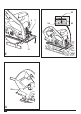
Fitting and removing the parallel fence (g. E)
The parallel fence is used to saw in a straight line parallel to
the edge of the workpiece.
Fitting
u Loosen the locking knob (21).
u Insert the parallel fence (12) through the openings (22).
u Slide the parallel fence into the desired position.
u Tighten the locking knob.
Removing
u Loosen the locking knob (21).
u Pull the parallel fence off the tool.
Use
Warning! Let the tool work at its own pace. Do not overload.
This tool can be used in the right hand or the left hand.
Warning! Carefully guide the cable in order to avoid
accidentally cutting it.
Adjusting the depth of cut (g. D)
The depth of cut should be set according to the thickness of
the workpiece. It should exceed the thickness by approx. 2 mm.
u Loosen the knob (5) to unlock the saw shoe.
u Move the saw shoe (11) into the desired position. The
corresponding depth of cut can be read from the scale (6).
u Tighten the knob to lock the saw shoe in place.
Adjusting the mitre angle (g. E)
This tool can be set to mitre angles between 0° and 45°.
u Loosen the locking knob (7) to unlock the saw shoe.
u Move the saw shoe (11) into the desired position. The
corresponding mitre angle can be read from the scale (8).
u Tighten the locking knob to lock the saw shoe in place.