7-1/4 IN. COMPOUND MITER SAW INSTRUCTION MANUAL CATALOG NUMBER M1850BD TYPE 2 Thank you for choosing Black+Decker! PLEASE READ BEFORE RETURNING THIS PRODUCT FOR ANY REASON. If you have a question or experience a problem with your Black+Decker purchase, go to http://www.blackanddecker.com/instantanswers If you can’t find the answer or do not have access to the Internet, call 1-844-437-5095 from 8:30 am to 5 p.m. EST Mon. - Fri. to speak with an agent.
SAFETY GUIDELINES - DEFINITIONS It is important for you to read and understand this manual. The information it contains relates to protecting YOUR SAFETY and PREVENTING PROBLEMS. The symbols below are used to help you recognize this information. ! DANGER : Indicates an imminently hazardous situation which, if not avoided, will result in death or serious injury. ! WARNING : Indicates a potentially hazardous situation which, if not avoided, could result in death or serious injury.
tool. Carrying power tools with your finger on the switch or energizing power tools that have the switch on invites accidents. d) Remove any adjusting key or wrench before turning the power tool on. A wrench or a key left attached to a rotating part of the power tool may result in personal injury. e) Do not overreach. Keep proper footing and balance at all times. This enables better control of the power tool in unexpected situations. f) Dress properly. Do not wear loose clothing or jewelry.
• Push the saw through the workpiece. Do not pull the saw through the workpiece. To make a cut, raise the saw head and pull it out over the workpiece without cutting, start the motor, press the saw head down and push the saw through the workpiece. Cutting on the pull stroke is likely to cause the saw blade to climb on top of the workpiece and violently throw the blade assembly towards the operator. • Never cross your hand over the intended line of cutting either in front or behind the saw blade.
• Do not use this saw to cut tree limbs or logs. • Never use blades recommended for operation at less than 5000 RPM. • Do not use this saw to cut fiber cement board. This miter saw is not intended to cut fiber cement board. PROPOSITION 65 WARNING ! WARNING Drilling, sawing, sanding or machining wood products can expose you to wood dust, a substance known to the State of California to cause cancer. Avoid inhaling wood dust or use a dust mask or other safeguards for personal protection.
ELECTRICAL REQUIREMENTS AND SAFETY ! WARNING Double insulation does not take the place of normal safety precautions when operating this tool. To avoid electrocution: • Use only identical replacement parts when servicing a tool with double insulation. Servicing should be performed by a qualified technician. • Do not use power tools in wet or damp locations or expose them to rain or snow. POWER SUPPLY AND MOTOR SPECIFICATIONS The AC motor used in this saw is a universal, nonreversible type.
• Most motor troubles may be traced to loose or incorrect connections, overload, low voltage or inadequate power supply wiring. Always check the connections, the load and supply circuit if the motor doesn’t run well. Check minimum gauge for the length of cord you are using on the chart below. ! CAUTION In all cases make certain the receptacle in question is properly grounded. If you are not sure, have a certified electrician check the receptacle.
FREEHAND – Performing a cut without using a fence (guide), hold down or other proper device to prevent the workpiece from twisting during the cutting operation. HEEL – Misalignment of the blade. KERF – The width of a saw cut, determined by the thickness and set of the blade. KICKBACK – sudden and unintended movement of the tool or workpiece. It is typically caused by binding or pinching of the workpiece.
SYMBOLS Your power tool and its Instruction Manual may contain “WARNING ICONS” (a picture symbol intended to alert you to, and/or instruct you how to avoid a potentially hazardous condition). Understanding and heeding these symbols will help you operate your tool better and safer. Shown below are some of the symbols you may see. SAFETY ALERT: Precautions that involve your safety. PROHIBITION WEAR EYE PROTECTION: Always wear safety goggles or safety glasses with side shields.
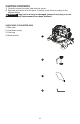
CARTON CONTENTS 1) Carefully remove the miter saw from the carton. 2) Separate and layout all of the parts. Carefully check them according to the diagram below. ! WARNING If any part is missing or damaged, please do not plug in or use the miter saw until replacements have been obtained. UNPACKING YOUR MITER SAW 1. Miter saw 2. Hold-down clamp 3. Dust bag 4.
FUNCTIONAL DESCRIPTION 2 1. Upper blade guard 2. Safety lock-off button 3. Switch handle 4. Motor 5. Lower blade guard 6. Fence 7. Miter scale 8. Table insert 9. Mounting hole 10. Base 11. Blade wrench storage 12. Hold-down clamp 13. Dust bag 14. ON/OFF trigger switch 15. Hold-down latch 16. Bevel scale 17. Miter table locking lever 18. Hand hold for transportation 19. Turn table 20.
TOOLS NEEDED TO REMOVE OR INSTALL BLADE ASSEMBLY AND ADJUSTMENTS ! Supplied WARNING • To avoid injury, do not connect this miter saw to the power source until it is completely assembled and adjusted, and you have read and understood this Instruction Manual. • To reduce the risk of injury, turn unit off and disconnect it from power source before installing and removing accessories, before adjusting or when making repairs. An accidental start-up can cause injury.
Unlocking NOTE: To empty the dust bag, squeeze the metal collar and remove from exhaust port. Open zipper on underside of bag and empty into waste container. IMPORTANT: Check frequently and empty bag before it gets full. • Push down slightly on the switch handle (1). • Pull out the hold-down latch (2). • Allow the cutting head to rise to the uppermost position.
• NEVER cut metals or masonry products with this tool. This miter saw is designed for use on wood and wood-like products only. • Never depress the arbor lock button while the blade is under power or coasting. E 1 • Unplug the saw from the outlet. • Raise the miter saw to the upright position. • Loosen the cover plate screw (1) with a Phillips screwdriver. (Figure H) • Rotate the cover plate (2) to expose the arbor bolt (3). 2 F 2 H 1 2 3 BLADE WRENCH STORAGE (FIG.
• Rotate the cover plate (2) back to its original position until the slot in the cover plate engages with the cover plate screw (1). Tighten the screw with a Phillips screwdriver. • Verify the operation of the guard. Make sure it does not bind or stick. • Be sure the arbor lock button (4) is released so the blade turns freely by spinning the blade until the arbor lock disengages. (Figure I) J 6 3 7 5 ! WARNING • To avoid injury, never use the saw without the cover plate secure in place.
• For portable use, place the saw on a 3/4 in. thick piece of plywood. Bolt the base of the miter saw securely to the plywood using the mounting holes on the base. Use C-clamps to clamp this mounting board to a stable work surface at the worksite. (Figure L) • Place the saw on a firm, level work surface where there is room for handling and properly supporting the workpiece. • Support the saw on a level work surface. • Always bolt or clamp the saw to its support.
• Tilt the cutting arm to back to the right at 90°(0°) bevel and recheck for alignment. • Repeat above steps if further adjustment is needed. • Tighten locknut (3) and bevel lock handle (1) when alignment is achieved. • Tilt the cutting arm to the left to 45° bevel and recheck for alignment. • Repeat above steps until the blade is at 45° to the table. • Tighten bevel lock handle (1) and locknut (5) when alignment is achieved.
• Turn the adjustment bolt (2) out (counterclockwise) to decrease the cutting depth or in (clockwise) to increase the cutting depth. • Carefully rotate the blade manually to check for contact. Avoid touching blade points or edges. • Repeat until adjusted properly, and tighten the locknut (1) to secure the adjustment bolt (2) into position. MITER ANGLE POINTER ADJUSTMENT (FIGURE P) • Move the table to the 0° positive stop. • Loosen the screw (4) that holds the pointer (5) with a Phillips screwdriver.
OPERATING INSTRUCTIONS BEFORE USING THE MITER SAW ! WARNING • To reduce the risk of injury, turn unit off and disconnect it from power source before installing and removing accessories, before adjusting or when making repairs. An accidental start-up can cause injury. • To avoid mistakes that could cause serious, permanent injury, do not plug the tool in until the following steps are completed: • • • Completely assemble and adjust the saw, following the instructions.
• • • • Wear non-slip footwear. Tie back long hair. Roll long sleeves above the elbow. Noise levels vary widely. To avoid possible hearing damage, wear ear plugs when using any miter saw. • For dusty operations, wear a dust mask along with safety goggles. KEEP YOUR WORK AREA CLEAN Cluttered areas and benches invite accidents. ! WARNING To avoid burns or other fire damage, never use the miter saw near flammable liquids, vapors, or gases. • Plan ahead to protect your eyes, hands, face and ears.
USE EXTRA CAUTION WITH LARGE OR ODD SHAPED WORKPIECES • Use extra supports (tables, sawhorses, blocks, etc.) for workpieces large enough to tip. • Never use another person as a substitute for a table extension, or as an additional support for a workpiece that is longer or wider than the basic miter saw table, or to help feed, support, or pull the workpiece. • Do not use this saw to cut small pieces. If the workpiece being cut would cause your hand or fingers to be within 6 in.
• Release trigger switch and wait for all moving parts to stop before moving your hands and raising the cutting arm. • Unplug the miter saw. T Before freeing jammed material: • Release trigger switch. • Wait for all moving parts to stop. • Unplug the miter saw. W Proper cut U 6 in. Improper cut V 1 6 in.
X BEVEL CUT (FIGURE Z) • When a bevel cut is required, loosen the bevel lock handle (1). • Tilt the cutting head to the desired angle, as shown on the bevel scale (2). • The blade can be positioned at any angle, from a 90° straight cut (0° on the scale) to a 45° left bevel. Tighten the bevel lock handle (1) to lock the cutting head in position. Positive stops are provided at 0° and 45°. 2 1 3 Z BEFORE LEAVING THE SAW • Never leave tool running unattended. Turn power OFF.
CUTTING BOWED MATERIAL (FIGURE BB) ! WARNING To avoid injury from materials being thrown, always unplug the saw to avoid accidental starting and remove small pieces of material from the table cavity. • The table insert may be removed for this purpose, but always reattach table insert prior to performing a cutting operation. • A bowed workpiece (1) must be positioned against the fence and secured with a clamping device (2) as shown before cutting.
Most crown molding has a top rear angle (the section that fits flat against the ceiling) of 52°and a bottom rear angle (the section that fits flat against the wall) of 38°. In order to accurately cut crown molding for a 90° inside or outside corner, lay the molding with its broad back surface flat on the saw table. When setting the bevel and miter angles for compound miters, remember that the settings are interdependent; changing one changes the other, as well.
Bevel/Miter Settings NOTE: The chart below references a compound cut for crown molding ONLY WHEN THE ANGLE BETWEEN THE WALLS EQUALS 90°. KEY BEVEL SETTING MITER SETTING TYPE OF CUT Inside corner-Left side IL 33.9° 31.6° Right 1. Position top of molding against fence. 2. Miter table set at RIGHT 31.6°. 3. LEFT side is finished piece. Inside corner-Right side IR 33.9° 31.6° Left 1. Position bottom of molding against fence. 2. Miter table set at LEFT 31.6°. 3. LEFT side is finished piece.
CROWN MOLDING CHART Compound Miter Saw Miter and Bevel Angle Settings Wall to Crown Molding Angle 52/38° Crown Molding 45/45° Crown Molding Angle Between Walls Miter Setting Bevel Setting Miter Setting Bevel Setting 67 68 69 70 71 72 73 74 75 76 77 78 79 80 81 82 83 84 85 86 87 88 89 90 91 92 93 94 95 96 97 98 99 100 101 102 103 104 105 106 107 108 109 110 111 112 113 114 115 116 117 118 119 120 121 122 123 42.93 42.39 41.85 41.32 40.79 40.28 39.76 39.25 38.74 38.24 37.74 37.24 36.75 36.27 35.79 35.
MAINTENANCE ! Replace for the other side. To reassemble reverse the procedure. The ears on the metal end of the assembly go in the same hole the carbon part fits into. Tighten the cap snugly, but do not overtighten. Repeat for the carbon brush located on the other side of motor. NOTE: To reinstall the same brushes, first make sure the brushes go back in exactly the way they came out. This will avoid a break-in period that reduces motor performance and increases wear.
FULL TWO-YEAR HOME USE WARRANTY To empty the dust bag, remove the sawdust bag from the dust collection port. Open the zipper on the sawdust bag and empty out the sawdust inside. Close the zipper and reinstall the dust bag as described on page 13. ! WARNING Wear proper eye protection to keep debris from entering eyes when removing sawdust from unit. Black+Decker warrants this product for two years against any defects in material or workmanship.
LATIN AMERICA: This warranty does not apply to products sold in Latin America. For products sold in Latin America, check country specific warranty information contained in the packaging, call the local company or see the website for warranty information. TROUBLESHOOTING SAW OPERATION Problem Possible Cause Possible Solution • Blade hits table. • Misalignment. • See ADJUSTMENT -Setting Cutting Depth section. • Angle of cut • Miter table unlocked. not accurate. Can not adjust • Sawdust under table.
MOTOR Problem Possible Cause Possible Solution • Motor does not start. • Limit switch failure • Brush worn. • Replace limit switch. • Replace brushes. See MAINTENANCE section. • Verify there is electrical power at the outlet. • Fuse blown or circuit breaker tripped on home panel. • Brush spark when switch released. • Brush worn. • Replace Brushes. See MAINTENANCE section. • Contact Service Center. • Other. For assistance with your product, visit our website www.blackanddecker.
PARTS LIST 7-1/4 IN. MITER SAW PARTS LIST FOR MITER SAW - (1) Size I.D. Description I.D. Description X6VM BAG-DUST ASS'Y 1 X6WU COMPRESSION SPRING X6VN PC-GUARD ASS’Y 1 X6WV C-RING X6VR VISE ASS'Y 1 X6WW LOCATOR PIN 1 X6VW O-RING 1 X6WX HANDLE 1 ø10*ø1.9 Q’ty MODEL NO. M1850BD TYPE 2 Size Q’ty 1 ø8 1 X6VX CR. RE. PAN HD. SCREW M5*8 2 X6WY BALL BEARING 1 X6VY RING ø6 1 X6WZ FLOW GUIDE 1 X6VZ ROLLING WHEEL 1 X6X0 CR. RE. PAN HD.
7-1/4 IN. MITER SAW PARTS LIST FOR MITER SAW - (2) MODEL NO. M1850BD TYPE 2 I.D. Description Size Q’ty I.D. Description X6XX LOCK NUT M12 1 X6YQ HEX. SOC. HD. CAP BOLT Size Q’ty X6XY CR. RE. COUNT HD. SCREW 1 X6YR TILT POINTER 1 X6XZ LOCK NUT M5 1 X6YS TABLE 1 X6Y0 SUPPORT PLATE 1 X6YY FENCE X6Y1 HEX. SOC. HD. CAP BOLT M5*12 2 X6YZ HEX. SOC. HD.
7-1/4 IN. MITER SAW SCHEMATIC MODEL NO.