
Installation guide

Appendix B: Technical Specifications
BlackDiamond X8 Series Switches Hardware Installation Guide
114
Connector Pinouts
Table 15 shows the pinouts for the RJ-45 console port on the BlackDiamond X8 switch.
Table 16 shows the pinouts for an RJ-45-to-DB-9 adapter.
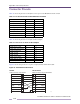
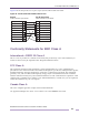
Figure 63 shows the pinouts for a 9-pin to 25-pin (RS-232) null-modem cable.
Figure 63: Null-modem Cable Pinouts
Table 15: RJ-45 Console Port on BlackDiamond X8 Switch
Function Pin Number Direction
CTS (clear to send) 1 In
DTR (data carrier detect) 2 Out
TXD (transmit data) 3 Out
GND (ground) 4 —
GND (ground) 5 —
RXD (receive data) 6 In
DSR (data set ready) 7 In
RTS (request to send) 8 Out
Table 16: Pinouts for an RJ-45 to DB-9 Adapter
Signal RJ-45 Pin DB-9 Pin
CTS (clear to send) 1 8
DTR (data carrier detect) 2 6
TXD (transmit data) 3 2
GND (ground) 4 5
GND (ground) 5 5
RXD (receive data) 6 3
DSR (data set ready) 7 4
RTS (request to send) 8 7
Screen
TxD
RxD
Ground
RTS
CTS
DSR
DCD
DTR
Cable connector: 9-pin female
Switch
Cable connector: 25-pin male/female
25pin
PC/Terminal
Screen
RxD
TxD
Ground
RTS
DTR
CTS
DSR
DCD
Shell
3
2
5
7
8
6
1
4
1
3
2
7
4
20
5
6
8