INSTALLER: Leave this manual with the appliance. CONSUMER: Retain this manual for future reference. These instructions are supplementary to the Installation and Operating Instructions supplied with the fireplace and should be kept together. Refer to the Installation and Operating Instructions for proper gas supply, safety requirements and operating instructions TC30 BLACK DIAMOND BURNER KIT INSTRUCTIONS PART# TC30.NG03.C For TC30 Series C 100308-12 TC30.NG03.C 5056.429.
Contents of Package A B G C J F I D H E NOTE: MUST BE USED WITH PORCELAIN PANEL SET PART# TC30.PNLPBKB A MANIFOLD ASSEMBLY (including supply tube) B BURNER TUBE C BURNER SHIELD D MEDIA SPACER, Center E MEDIA SPACER, Front F MEDIA SPACER, Rear G HARDWARE PACKAGE H 5 lbs. GLASS MEDIA I BURNER TRAY J PILOT SHIELD (including pilot and pilot supply tube) TC30.NGO3.
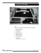
Black Diamond Burner Installation Fig #1 A porcelain panel set must be used in conjunction with the installation of the burner assembly. See Installation and Operating Instructions manual for details. NOTE: Plug the 4 vacant holes in the bottom of the firebox with 1/2” screws, as they are not required to attach this style of burner. 1. Remove three screws from the rear of the firebox. Attach the manifold bracket to the rear of the firebox with the three screws previously removed. (Fig.
5. Install burner shield by tipping the shield into the firebox. Route pilot up through the opening in the burner shield. (Fig. #5) Fig #5 INSTALLING BURNER SHIELD Fig #6 6. Attach the burner tray to the burner shield using two screws at the back of the tray. (Fig. #6) BURNER TRAY PLACEMENT 7. Attach pilot shield to burner tray with two screws. (Fig. #7) Fig #7 PILOT SHIELD ATTACHMENT TC30.NGO3.
8. Front and rear media spacers are now installed. (Fig. #8 & 9) Fig #8 REAR MEDIA SPACER Fig #9 FRONT MEDIA SPACER Fig #10 9. Install burner by tilting burner inlet through tray. Ensure that the orifice has entered the inlet tube. (Fig#10). BURNER INSTALLATION Set the air shutter to fully open for Propane or fully closed for Natural gas. TC30.NGO3.
11. Install the center media spacer and secure to the tray with two 1 1/2” screws. (Fig. #11 & 12) Three holes must line up to set each screw. Fig #11 CENTER MEDIA SPACER Fig #12 Fig #13 GLASS MEDIA PLACEMENT 12. Apply just enough glass media to cover the burner assembly. (Fig #13 & 14) Fig #14 FINISHED INSTALLATION OF GLASS MEDIA NOTE: Too much glass media over the burner will cause sooting with the use of propane gas. TC30.NGO3.
Propane Conversion WARNING This conversion kit shall be installed by a qualified service agency in accordance with the manufacturer's instructions and all applicable codes and requirements of the authority having jurisdiction. If the information in these instructions is not followed exactly, a fire, explosion or production of carbon monoxide may result causing property damage, personal injury or loss of life. The qualified service agency is responsible for the proper installation of this kit.
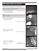
. Remove the minimum rate screw located in the valve. (Fig. #19) Fig #19 The minimum rate screw is sealed with an o-ring. Use a thin bladed screwdriver to back the screw out to the limit of the threads. A groove on the screw body will be visibe just above the valve body. Insert a thin tool (knife blade or thin screwdriver blade) into the groove and gently pry the screw up. Minimum rate screw It helps to rotate the screw while lifting on it. Fig #20 Minimum rate screw Fig #21 9.
Gas Pressure Check Note: To test the gas pressure, turn off the gas supply before removing the plug from the supply pressure test port or manifold pressure test port. Fig #25a Verify gas pressures with the fireplace lit and on the highest setting. SUPPLY PRESSURE MANIFOLD PRESSURE Fig #24 1. Remove the plug from the pressure test port. The plug is located between the right side lintel and firebox side. (Fig. #24) Fig #25 2. Thread the extension test fitting into the open test port. (Fig. #25) 3.
Burner Flame Adjustment The air shutter on the burner tube controls the primary combustion air to the gas burner and is preset at the factory for natural gas fuel. Some adjustment may be necessary to obtain desired flame and to eliminate carbon deposits. Evaluate flame appearance after the fireplace has reached operating temperature. See Fig. #28 for proper flame pattern. Open primary air shutter if the glass media, glass, and firebox have carbon accumulation and/or the flames are long, dark and stringy.
Replacement Parts (WHEN ORDERING, INCLUDE PART NUMBER WITH DESCRIPTION) ITEM ............ DESCRIPTION .................................................................... PART NO. #1................. TC30 BLACK DIAMOND BURNER KIT ............................ TC30.NG03.C #2................. BURNER TUBE ................................................................... TC36. 5011835 #3................. PILOT ASSEMBLY, CONVERTIBLE.............. ................... 5005.025 #4.................
Technical support: 1-877-715-2664 Web site: www.townandcountryfireplaces.net 2975 Allenby Rd.