
User Manual

30
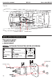
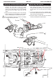
1) Using a modeling knife, cut one length of silicon
fuel line (the length of silicon fuel line is calculated by
how the weighted clunk should rest about 8mm away
from the rear of the tank and move freely inside the
tank). Connect one end of the line to the weighted
clunk and the other end to the nylon pick up tube in the
stopper.
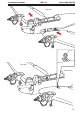
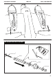
2) Carefully bend the second nylon tube up at a 45
degree angle (using a cigarette lighter). This tube will
be the vent tube to the muffler.
3) Carefully bend the third nylon tube down at a 45
degree angle (using a cigarette lighter). This tube will
be vent tube to the fueling valve.
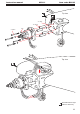
When the stopper assembly is installed in the
tank, the top of the vent tube should rest just below the
top surface of the tank. It should not touch the top of
the tank.
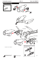
4) Test fit the stopper assembly into the tank. It may
be necessary to remove some of the flashing around
INSTALLING THE FUEL TANK
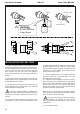
6) When satisfied with the alignment of the stopper
assembly tighten the 3mm x 20mm machine screw
until the rubber stopper expands and seals the tank
opening. Do not over tighten the assembly as this
could cause the tank to split.
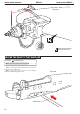
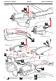
7) Using a modeling knife, cut 3 lengths of fuel line.
Connect 2 lines to the 2 vent tubes and 1 line to the
fuel pickup tube in the stopper.
8) Feed three lines through the fuel tank compart-
ment and through the pre-drilled hole in the firewall.
Pull the lines out from behind the engine, while guiding
the fuel tank into place. Push the fuel tank as far
forward as possible, the front of the tank should just
about touch the back of the firewall.
Blow through one of the lines to ensure the fuel lines
have not become kinked inside the fuel tank compart-
ment. Air should flow through easily.
Do not secure the tank into place permanently
until after balancing the airplane. You may need to
remove the tank to mount the battery in the fuel tank
compartment.
8) Secure the fuel tank.
Bend 40
0
degree
Bend 40
0
degree
40 degree bend
40
0
40
0
9mm
12mm
6mm
!
Inflame
Do not overheat,
it may break.
WARNING
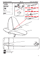
Instruction manual HE-111 Item code: BH143
INSTALLATION THE FUEL TANK