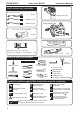
Instruction Manual Book Item code: BH178 Focke Wulf 190A Glow and EP INCLUDED AIR RETRACT LANDING GEAR WITH OLEO STRUTS. ALL BALSA - PLY WOOD CONSTRUCTION. COVERED IN A HEAT-SHRINK FILM WITH PRINTED. 95% ALMOST READY TO FLY SPECIFICATION: - Wingspan: 2,600mm (102.4in). - Length: 2,230mm (87.8in). - Weight: 15kg (33lbs). - Wing area: 117 dm². - Wing loading: 128.2 g/dm². - Wing type: Naca Airfoil. - Servo mount: 42mm x 21mm.
FOCKE WULF Item code: BH178 Instruction Manual TABLE OF CONTENTS Introduction...............................................2 Installing the rudder linkages...................25 Warranty....................................................3 Installing the tail gear...............................27 Disclaimer.................................................3 Secure the wing to the fuselage..............31 Safety precaution......................................3 Installing the engine.................
FOCKE WULF Item code: BH178 WARRANTY Black Horse Model guarantees the component parts in this kit to be free from defects in both material and workmanship at the date of purchase by the purchaser. This warranty does not cover cosmetic damage or damage due to acts of God, accident, misuse, abuse, negligence, commercial use, or modification of or to any part of the Product.
FOCKE WULF Item code: BH178 FLIGHT WARNINGS When ready to fly, first extend the transmitter aerial. Switch on the transmitter. Switch on the receiver. Check that the wings are correctly fitted to the fuselage. Operate the control sticks on the transmitter and check that the control surfaces move freely and in the CORRECT directions. Check that the transmitter batteries have adequate power. ALWAYS take off into the wind.
FOCKE WULF Item code: BH178 Instruction Manual • Officially designated AMA Air Show Teams (AST) are authorized to use devices and practices as defined within the Team AMA Program Document. (AMA Document #718.) (j) Not operate a turbine-powered aircraft, unless in compliance with the AMA turbine regulations. (AMA Document #510-A.) 3.
FOCKE WULF Item code: BH178 Instruction Manual PARTS LISTING (NOT INCLUDED). Servo extension leads. ................. 2 pcs. Engine: 120cc gas .....220mm 2 pcs. Motor: BOOST 180 .....620mm 2 pcs. LiPo. 12S - 44,4V - 6,000mAh. BATTERY 2 Packs ESC Servos Size: ( 39.9 x 20.1 x 38.1)mm. Torque: 6V (11.3kg/cm), 7.4V (12.9kg/cm).......9pcs ESC: 120A........1 pcs. TOOLS & SUPPLIES NEEDED 10 9 8 7 6 5 4 3 2 1 Straight edge ruler. cm EPOXY A EPOXY B 30 minute epoxy. 5 minute epoxy.
FOCKE WULF 1 2 3 4 5 6 7 8 9 10 11 12 Item code: BH178 13 : 14 : 15 : 16 : 17 : 18 : : Top hatch fuselage ( 7a : Wood frame hatch, 19 7b: Pilot seat, 7c: Canopy, 7d: Pilot doll, : Fuselage. : Wing panel ( 2a, 2b ). : Horizontal stabilizer ( 3a, 3b ). : Vertical stabilizer : Aluminium wing dihedral brace. : Aluminium tube horizontal stabilizer. Instruction Manual Engine mount. Plastic exhaust. Spinner ( 95mm ). : Valve one way. : Fuel Tank (8a: Clunk; 8b : Stopper (three line)).
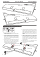
FOCKE WULF Item code: BH178 Instruction Manual INSTALLING THE FLAP CONTROL HORNS AND LINKAGES 3x15mm Tp Screw -----------8 3x12mm Cap Screw - - - - - - - - - - 10 2.6x90mm Push rod --- 4 2 Ball link Horn 3mm Hex Nut ----4 ---2 3mm Flat Washer ----4 2x10mm Tp Screw - - - - 16 Horn ----2 Plastic ----2 Flap Flap Flap m 0m 9 .6x 2 ---8 Pu sh rod Ball link 3x15mm Tp Screw 3x12mm Cap Screw Flap Top Side Horn Push rod Ball link Assemble left and right sides the same way.
FOCKE WULF Item code: BH178 Instruction Manual INSTALLING THE AILERONS AND FLAPS 44mm Pinned hinge - - - - - - - - - - - - - 12 67mm Pinned hinge -------------8 Bottom Side Ailer on Flap 44mm Pinned hinge 67mm Pinned hinge Flap Push rod Bottom Side Make certain the hinges are adequately secured with glue. If they come loose in flight accidents may result. Assemble left and right sides the same way.
FOCKE WULF Item code: BH178 Instruction Manual Right wing Bottom Side Left wing Bottom Side INSTALLING THE AILERON AND FLAP SERVO 1. Install the rubber grommets and brass eyelets onto the aileron servo. 2. Using a modeling knife, remove the covering from over the pre-cut servo arm exit hole on the aileron servo tray / hatch. This hole will allow the servo arm to pass through when installing the aileron pushrods 3. Place the servo into the servo tray.
FOCKE WULF 2 For Flap Item code: BH178 2 For Flap 3mm Flat Washer 3mm Cap Screw Instruction Manual 2 For Flap 3mm Hex Nut 2 Screw 2mm 2 For Flap For Flap Cut off shaded portion carefully. Drill holes using the stated. Assemble left and right sides the same way. 1.5mm (in this case 1.5mm ).
FOCKE WULF 2 Item code: BH178 m m 90 x 2.6 2 2 Aileron h us P Instruction Manual Aileron 3mm Flat Washer rod Ball Link 3mm Hex Nut 2 Aileron 3x12mm Cap Screw Aileron mm Tp Screw 2mm 2 Aileron 2x10mm Tp Screw 1.5mm Cut off shaded portion carefully. 12 Pay close attention here. Drill holes using the stated. ). 2mm (in this case 2mm The number of times same way Assembly 2 the (in this case twice). Assemble left and right sides the same way.
FOCKE WULF Item code: BH178 For Aileron Instruction Manual For Flaps 2x10mm Tp Screw 1 Ailer on Bottom Side Flap 1 Tie the string 2 Pull out servo cord with string. Aileron Aileron 3x15mm Tp Screw Horn 2 Aileron Aileron Horn 3x12mm Cap Screw Aileron Aileron C.A Ailer on Flap Bottom Side Assemble left and right sides the same way. Cut off shaded portion carefully. Apply instant glue C . A (C.A glue, super glue).
FOCKE WULF Item code: BH178 Instruction Manual INSTALLING THE AIR RETRACTABLE LANDING GEAR 6x60mm Socket Head Cap Screw ----2 6mm Flat Washer ------------2 6mm Collar ------------2 4x20mm Button Head Cap Screw ----8 4mm Spring Washer ----8 3x4mm SetScrew ----6 2x10mm Tp Screw ----8 3x6mm Button Head Cap Screw - - - - 12 160mm Install the tube and spring to the air retract 14 * Using a modeling knife, carefully remove the film covering from the wing gear tray.
FOCKE WULF 6mm Collar Item code: BH178 Instruction Manual 6mm Flat Washer 6x60mm Socket Head Cap Screw 4x20mm Socket Head Cap Screw 4mm Flat Washer Bottom Side Assemble left and right sides the same way. Drill holes using the stated. ).
FOCKE WULF Item code: BH178 Instruction Manual Bottom Side 2x10mm Tp Screw Bottom Side Bottom Side Assemble left and right sides the same way.
FOCKE WULF Item code: BH178 94mm Instruction Manual 94mm 67mm Bottom Side 3x6mm Button Head Cap Screw Bottom Side Bottom Side Assemble left and right sides the same way.
FOCKE WULF Item code: BH178 Instruction Manual Gun --------4 L R Bottom Side Gun C .A L R Bottom Side C .A L Apply instant glue (C.A glue, super glue). Assemble left and right R sides the same way. HORIZONTAL STABILIZER INSTALLATION 1. Using a modeling knife, cut away the covering from the fuselage for the stabilizer and remove it. 2. Remove the covering from the stabilizer.
FOCKE WULF Instruction Manual Make certain plane is aligned accurately per the diagram. A mis-aligned plane can fly erraticaliy and cause accidents. Warning! L Item code: BH178 R Pinned Hinge L Aluminium Tube R 12mm ---1 Fuselage Top Side 374mm L Assemble left and right R sides the same way.
FOCKE WULF Fuselage Top Side 20 Item code: BH178 Instruction Manual
FOCKE WULF 4x16mm Button Head Cap Screw -----------4 Item code: BH178 4mm Flat Washer 4mm Flat Washer -----------4 Fuselage Bottom Side 4mm Flat Washer 4x16mm Button Head Cap Screw RUDDER INSTALLATION 44mm Pinned Hinge ----5 Fuselage Top Side Pinned Hinge 21 Instruction Manual 4x16mm Button Head Cap Screw
FOCKE WULF Item code: BH178 Cut off shaded portion Instruction Manual Apply epoxy glue INSTALLING THE ELEVATOR LINKAGES Repeat these step as installing the aileron linkages. Aluminum ball Horn - - - - - - - 2 ----------4 ----------4 3x12mm Cap Screw ------4 2.
FOCKE WULF Item code: BH178 Instruction Manual Fuselage Bottom Side 3x15mm Tp Screw 2 2 2 Horn 3x12mm Cap Screw Cut off shaded portion carefully. 23 Assemble left and right sides the same way The number of times same way Assembly 2 the (in this case twice).
FOCKE WULF Item code: BH178 3x12mm Button Head Cap Screw Instruction Manual 3x12mm Button Head Cap Screw 3mm Flat Washer 3mm Flat Washer 2 2 3mm Hex Nut 2 3mm Hex Nut Fuselage Top Side Elevator Servo Elevator Servo 24
FOCKE WULF Item code: BH178 Instruction Manual INSTALLING THE RUDDER LINKAGES Aluminum ball ------------2 ------------4 Horn -----1 3x12mm Cap Screw Locknut ------------4 Horn ------2 3 x 30mm Connector ------------4 3x12mm Cap Screw 3x15mm Tp Screw -------2 1500mm Cable rod ------------2 2 3x12mm Tp Screw 3mm Crimp 2 2 3 5 4 1 Cable rod Fuselage Bottom Side Cut off excess. 25 Assemble left and right sides the same way Drill holes using the stated. 3mm (in this case 3mm ).
FOCKE WULF Item code: BH178 Instruction Manual 3x12mm Button Head Cap Screw 3mm Flat Washer 2 2 3mm Hex Nut 2 3x12mm Button Head Cap Screw 90 o 3mm Flat Washer Servo Rudder Ball Link 3mm Connector 3mm Hex Nut 2 4 3 Hex Nut Cab link 1 5 Cut off excess. Must be purchased separately! Cut off shaded portion carefully. Pay close attention here. 1.5mm Drill holes using the stated. (in this case 1.5mm ).
FOCKE WULF Item code: BH178 Instruction Manual Fuselage Top Side Rudder servo INSTALLING THE TAIL GEAR 1400mm Cable rod -----2 27 Aluminum ball ------------2 ------------4 4x12mm Socket Head Cap Screw --------1 3 x 30mm Connector 4mm Spring Washer ----------4 Locknut ------------4 ------------2 3x12mm Button Head Cap Screw -----2 3mm Flat Washer -----2 3mm Hex Nut -----2
FOCKE WULF Item code: BH178 2 Crimp Instruction Manual Crimp 3 4 5 1 Cable rod Cable rod 4mm Spring Washer 4x12mm Socket Head Cap Screw 28
FOCKE WULF Item code: BH178 Fuselage Bottom Side Fuselage Bottom Side 29 Instruction Manual
FOCKE WULF Item code: BH178 Instruction Manual Fuselage Bottom Side Close / Open 3x12mm Button Head Cap Screw 90 o 3mm Flat Washer Servo tail gear Ball Link 3mm Connector 3mm Hex Nut 2 4 3 Hex Nut Cab link 1 5 30
FOCKE WULF Item code: BH178 Instruction Manual Fuselage Top Side Tail Gear Tail Gear SECURE THE WING TO THE FUSELAGE Attach the wings to the fuselage and secure the wing panels. 32mm Aluminium tube.
FOCKE WULF Item code: BH178 Instruction Manual Fuselage Top Side 665mm Aluminium Tube Fuselage Top Side 995mm Aluminium Tube Fuselage Top Side 32
FOCKE WULF Item code: BH178 Instruction Manual Fuselage Top Side Fuselage Top Side 4x15mm Screw 33 4x15mm Screw
FOCKE WULF Item code: BH178 Instruction Manual INSTALLING THE ENGINE 16x50mm Aluminium -------4 6mm Flat Washer -------4 M6 Blind Nut mm Flat Washer --------4 -------4 550mm Pushrod wire 6x80mm Socket Head 6mm Spring Washer mm Rubber Washer Cap Screw -------4 -------4 -----4 6mm Hex Nut -----2 Connector --------1 -------4 Fuselage Top Side 6mm Flat Washer Zip tie 6mm Flat Washer 6mm Spring Washer 6mm Rubber Washer 16x50mm Aluminium 6mm Flat Washer 6x80mm Socket Head Cap Screw 6mm Hex Nut
FOCKE WULF Item code: BH178 ESC Zip tie mm 550mm Pushrod wire 35 Instruction Manual Fuselage Top Side
FOCKE WULF Item code: BH178 Instruction Manual INSTALLING THE THROTTLE 1. Plug the throttle servo into the receiver and turn on the radio system. Check to ensure that the throttle servo output shaft is moving in the correct direction. When the throttle stick is moved forward from idle to full throttle, the throttle barrel should also open and close using this motion. If not, reverse the direction of the servo, using the transmitter.
FOCKE WULF Item code: BH178 Instruction Manual INSTALLING THE STOPPER 30mm Screw Rubber Aluminum Rubber Aluminium Inflame ! WARNING Do not overheat, it may break.
FOCKE WULF Item code: BH178 INSTALLING THE FUEL TANK 1. Using a modeling knife, cut one length of silicon fuel line (the length of silicon fuel line is calculated by how the weighted clunk should rest about 5mm away from the rear of the tank and move freely inside the tank). Connect one end of the line to the weighted clunk and the other end to the nylon pick up tube in the stopper. 2. Carefully bend the second nylon tube up at a 45 degree angle (using a cigarette lighter).
FOCKE WULF Item code: BH178 Instruction Manual INSTALLING THE ..... R L Fuselage Top Side L L C .A L 39 L Assemble left and right R sides the same way. C .A Apply instant glue (C.A glue, super glue).
FOCKE WULF Item code: BH178 Instruction Manual MOUNTING THE COWL 1. Remove the muffler and needle valve assembly from the engine. Slide the fiberglass cowl over the engine. 4. While holding the cowl firmly in position, drill four 1,6mm pilot holes through both the cowl and the side edges of the firewall. 2. Measure and mark the locations to be cut out for engine head clearance, needle valve, muffler.
FOCKE WULF Item code: BH178 Instruction Manual 309mm 332mm m 210m Fuselage Top Side A B L Plastic A B 41 Apply epoxy glue.
FOCKE WULF Item code: BH178 Instruction Manual Fuselage Top Side L 3x12mm Tp Screw Fuselage Top Side L 42
FOCKE WULF Item code: BH178 3x12mm Tp Screw Fuselage Top Side 2.5mm L C.A 3x12mm Tp Screw 3x12mm Tp Screw C.A R 3x12mm Tp Screw 2.5mm 43 Drill holes using the stated. (in this case 2.5mm ). Apply instant glue C . A (C.A glue, super glue). 2.
FOCKE WULF Item code: BH178 INSTALLING VALVE CONTROL Valve one way Instruction Manual Valve control Connector Air tank 3 way conector 4 way conector Air line sets CLEANING THE VALVE Must be purchased separately! 44
SERVO 3 WAY CONNECTOR 3 WAY CONNECTOR PRESURE TANK MAIN GEAR MAIN GEAR AIR UP, AIR DOWN WITH OLEO STRUTS.
FOCKE WULF Item code: BH178 Valve control servo Instruction Manual Fuselage Top Side Zip tie Air tank Air tank Zip tie INSTALLING THE RECEIVER AND BATTERY 1. Plug the servo leads and the switch lead into the receiver. You may want to plug an aileron extension into the receiver to make plugging in the aileron servo lead easier when you are installing the wing. Plug the battery pack lead into the switch. 2. Wrap the receiver and battery pack in the protective foam to protect them from vibration.
FOCKE WULF Item code: BH178 mm Tp Screw Instruction Manual Fuselage Top Side Plywood On mm Tp Screw Off Switch Foam Pad Battery 47 Tape Switch Receiver Battery Must be purchased separately!
FOCKE WULF Item code: BH178 Instruction Manual INSTALLING COCKPIT FUSELAGE Position the canopy so the rear frame on the canopy is aligned with the rear edge of the cockpit opening. Use canopy glue to secure the canopy to the canopy hatch. Use low-tack tape to hold the canopy in position until the glue fully cures. Wrap the tape completely around the canopy hatch. A B Adhesive tape.
FOCKE WULF Item code: BH178 Instruction Manual Fuselage Top Side L A B A B Fuselage Top Side Open / Close L 49 A B Apply epoxy glue.
FOCKE WULF Item code: BH178 Instruction Manual Open / Close Fuselage Top Side L Adhesive tape. INSTALLING THE PROPELLER 3x12mm Socket Head Cap Screw ------------4 95mm Fuselage Top Side L 5mm Drill holes using the stated. 5mm (in this case 5mm ).
FOCKE WULF Item code: BH178 Instruction Manual Fuselage Top Side L 3x12mm Socket Head Cap Screw Fuselage Top Side L 51
FOCKE WULF Item code: BH178 INSTALLING KEINE BOMBE! Instruction Manual Keine Bombe! Aluminum ----4 Pinned hinge --------4 4x16mm Socket Head Cap Screw --------3 4x12mm Socket Head Cap Screw --------4 3x10mm Tp Screw --------4 4mm Spring Washer -------4 Plastic Wood A B A B 3x10mm Tp Screw A B Apply epoxy glue.
FOCKE WULF Item code: BH178 Instruction Manual A B A B 80mm 55mm A B 53 Apply epoxy glue.
FOCKE WULF Item code: BH178 Instruction Manual 4x16mm Socket Head Cap Screw 4mm Spring Washer Fuselage Bottom Side 54
FOCKE WULF Item code: BH178 Instruction Manual 4mm Spring Washer Fuselage Bottom Side 55 4x12mm Socket Head Cap Screw
FOCKE WULF Item code: BH178 LATERAL BALANCE BALANCING 1. It is critical that your airplane be balanced correctly. Improper balance will cause your plane to lose control and crash. Instruction Manual ! After you have balanced a plane on the C.G. You should laterally balance it. Doing this will help the airplane track straighter. THE CENTER OF GRAVITY IS LOCATED 54mm ( 2,126 in ) BACK FROM THE LEADING EDGE OF THE WING, AT THE FUSELAGE. BALANCE A PLANE UPSIDE DOWN WITH THE FUEL TANK EMPTY. 1.
FOCKE WULF Item code: BH178 Instruction Manual 6mm Cut off excess. In order to obtain the CG specified, reposition the receiver and other equipment. If not obtain the CG specified, add a weight and adjust. CG Do not fly before confirming the correct location of the CG. If the CG is incorrect, you lose control of your airplane which leads to accidents.
FOCKE WULF Item code: BH178 Instruction Manual CONTROL THROWS FLIGHT PREPARATION PRE FLIGHT CHECK 1) We highly recommend setting up a plane using the control throws listed. 2) The control throws should be measured at the widest point of each control surface. 3) Check to be sure the control surfaces move in the correct directions. LOW RATE 1) Completely charge your transmitter and receiver batteries before your first day of flying.
FOCKE WULF Item code: BH178 Instruction Manual 25mm Flap Control FOR YOUR RADIO INSTALLATION BASIC CONNECTION FOR AIRPLANE AND ADJUSTMENT OF SERVOS Example of connection For more information, refer to radio system instruction manual. Follow instruction manual of Engine and Battery.
FOCKE WULF Item code: BH178 Instruction Manual MAIN GEAR DIMENSIONAL DETAIL 70mm 54mm 40mm 32mm 314mm 45mm 65mm 158mm 160mm 45mm 6.
FOCKE WULF Item code: BH178 Instruction Manual DECORATION 6 6 5 5 1 1 7 Reifendruck 5 atü 4 Hier aufbocken 5 3 8 1 7 Reifendruck 5 atü Hier aufbocken 3 2 1 Bo e Ke in 2 4 m be ! 5 9 6 4 7 8 61 9 5
3x12mm Cap Screw 3x15mm Tp Screw 6mm Spring Washer 2mm mm Rubber Washer mm Flat Washer 3x12mm Cap Screw 3x12mm Cap Screw 3x15mm Tp Screw 2x10mm Tp Screw 3x12mm 3mm Hex Nut 3x15mm Tp Screw 3x12mm Cap Screw 4x4mm 2x10mm 6mm Hex Nut 2mm 6mm Rubber Washer 3x12mm Cap Screw 16x50mm Aluminium 3x12mm Cap Screw 3x15mm Tp Screw 6mm Flat Washer 3mm Hex Nut 3x12mm Cap Screw 3x1 3mm 3x15mm Tp Screw 3x12mm Cap Screw Aluminium tube Horizontal stabilizer 3x6mm Button Head Cap Screw 4x12mm Sock
I/C FLYING WARNINGS NEVER fly near power lines,aerials or other dangerous areas including airports, motorways etc. AL WAYS adjust the engine from behind the propeller, and do not allow any part of your body to be in line with the propeller. Always operate in open areas, away from factories, hospitals, schools, buildings and houses etc. NEVER fly your aircraft close to people or built up areas. D O N O T dispose of empty fuel containers on a fire, this can lead to an explosion.
I/C FLYING GUIDELINES When ready to fly, first extend the transmitter aerial. Operate the control sticks on the transmitter and check that the control surfaces move freely and in the CORRECT directions. ALWAYS land the model INTO the wind, this ensures that the model lands at the slowest possible speed. OFF - ON OFF - ON OFF - ON Switch on the transmitter. Check that the transmitter batteries have adequate power. Switch off the receiver. OFF - ON OFF - ON OFF - ON Switch on the receiver.