INSTRUCTION MANUAL BOOK ITEM CODE BH38. SPECIFICATION 1 Wingspan : 1,400 mm 1 Length : 1,460 mm 1 Weight : 3.8 kg 55 in. 57.5 in. 8.4 lbs. Parts listing required (not included): 1 Engine 1 Radio 1 Servo : 61-.91cu.in 2 stroke; 120 cu.in 4 stroke. : 04 channels. : 06 servos. Made in Vietnam.
ULTIMATE. This instruction manual is designed to help you build a great flying aeroplane. Please read this manual thoroughly before starting assembly of your ULTIMATE. Use the parts listing below to identify all parts. WARNING. Please be aware that this aeroplane is not a toy and if assembled or used incorrectly it is capable of causing injury to people or property. WHEN YOU FLY THIS AEROPLANE YOU ASSUME ALL RISK & RESPONSIBILITY.
INSTRUCTION MANUAL. SAFETY PRECAUTION. + This is not a toy + Be sure that no other flyers are using your radio frequency. + Do not smoke near fuel + Store fuel in a cool, dry place, away from children and pets. + Wear safety glasses. +The glow plug clip must be securely attached to the glow plug. + Do not flip the propeller with your fingers. + Keep loose clothing and wires away from the propeller. + Do not start the engine if people are near. Do not stand in line with the side of the propeller.
ULTIMATE. 1 4. Install servo tray with aileron servo into the wing as same as picture below. Remove covering. 2x10mm. 1 2. Drill 1,5mm pilot holes through the block of wood for each of the four mounting screws provided with the servo. Install servo into aileron servo tray as same as picture below: Aileron sero tray. Wing. Servo tray. 1 3. Using the thread as a guide and using masking tape, tape the servo lead to the end of the thread: carefully pull the thread out.
INSTRUCTION MANUAL. Aileron control horn. 1 3. Drill three 3mm holes through the ai- leron using the control horn as a guide and screw the control horn in place. Drill 6mm a hole diameter. Bottom of left lower wing 1 4. Install control horn as same as picture below. Nilon control clasp. Control horn. 3x40mm. M3 lock nut.
ULTIMATE. 1 3. Plug the aileron servo into the receiver and center the servo. Install the servo arm onto the servo. The servo arm should be perpendicular to the servo and point toward the middle of the wing. C/A glue. bend. 1 4. Locate one nylon servo arm, and using C/A glue. wire cutters,remove all but one of the arms. Using a 2mm drill bit, enlarge the third hole out from the center of the arm to accommodate the aileron pushrod wire. 1 5.
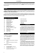
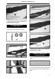
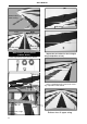
INSTRUCTION MANUAL. Top of left lower wing Top of left lower wing Drill hole. Repeat the procedure for the right lower wing half (bottom of right ). WING STRUT INSTALLATION (LOWER WING). Top of left lower wing Straight line Parts requirement. See pictures below: Secure Finishing Repeat the procedure for the right lower wing half (Top of right ). 245mm. JOINING THE WING HALVES (LOWER MAIN WING). 1 1. Locate the aluminium wing dihedral brace. Mark point old straight line 25mm. 1 2.
ULTIMATE. Bottom side of left lower a wing. Drill hole. Dowel. Left Top side of left lower a wing. Right Aluminium brace. Top side of right lower a wing. WING STRUT INSTALLATION (UPPER WING). Parts requirement. See pictures below: Repeat the procedure for the left upper wing half (Bottom of left ). Remove the covering. Straight line 245mm. Using a modeling knife, remove the covering at possition show below. Mark point old straight line Bottom side of right upper wing 8 18mm.
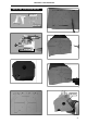
INSTRUCTION MANUAL. INSTALLING THE ENGINE MOUNT. 4x30mm. 3.5x25mm. 122mm. Drill holes.
ULTIMATE. FUEL TANK. INSTALLING THE STOPPER ASSEMBLY 1 1. The stopper has been pre-assembled at the factory. 1 5. Test fit the stopper assembly into the 1 2. Using a modeling knife, cut one length of tank. It may be necessary to remove some of the flashing around the tank opening using a modeling knife. If flashing is present, make sure none of it falls into the tank. 1 6.
INSTRUCTION MANUAL. Fuel tank. Rubber band. COWLING. 1 1. Slide the fiberglass cowl over the engine and line up the back edge of the cowl with the marks you made on the fuselage. 3x10mm. 1 2. While keeping the back edge of the cowl flush with the marks, align the front of the cowl with the crankshaft of the engine. The front of the cowl should be positioned so the crankshaft is in nearly the middle of the cowl opening. Hold the cowl firmly in place using pieces of masking tape.
ULTIMATE. Machine screw. INSTALLLING THE FUSELAGE SERVO. 1 1. Install the rubber grommets and brass collets into the elevator, rudder, and throttle servos. Test fit the servos into the servo tray. 1 2. Mount the servos to the tray using the mounting screws provided with your radio system. INSTALLING THE SPINNER. Install the spinner backplate, propeller and spinner cone. The spinner cone is held in place using two 3mm x 15mm wood screws. Elevator servo. Rudder servo. 12 Throttle servo.
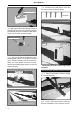
INSTRUCTION MANUAL. HORIZONTAL STABILIZER. 1 1. Using a modeling knife, cut the covering from the horizontal stabilizer and remove it. 1 2. Draw a center line onto the horizontal stabilizer. Then slide the horizontal into the fuselage. Remove covering. Remove covering. Cut the covering away from the slot. Temporary pin to keep hinge centered. Assemble then apply drops of thin C/A to center of hinge,on both sides. See pictures below: Check to mark sure the wing and stabilizer are paralell.
ULTIMATE. 1 3. Mark the shape of the vertical on the left and right sides onto the horizontal stabilizer using a felt-tip pen Pen. 1 4. Remove the stabilizer. Using the lines you just drew as a guide, carefully remove the covering from between them using a modeling knife. When cutting through the covering to remove it, cut with only enough pressure to only cut through the covering it’s self. Cutting into the balsa structure may weaken it. This could lead to possible failure during flight.
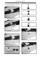
INSTRUCTION MANUAL. Assemble then apply drops of thin C/A to center of hinge,on both sides. 1 3. Mark the shape of the vertical on the left and right side on the rudder using a felt-tip pen. Pen. 1 4. Now, remove the rudder and using a modeling knife, carefully cut just inside the marked lines and remove the film of the rudder. Just as you did with the horizontal stabilizer, make sure you only press hard enough to cut the film, not the balsa rudder. C/A glue. 1 1.
ULTIMATE. Epoxy glue. CONTROL HORN - PUSHROD INSTALLATION. A. RUDDER: Rudder control horn install as same as the way of aileron control horn. Please see pictures below. 3mmx40mm. M3 lock nut. Nilon control clasp. Drill 6mm a hole of the mounting rudder control horn on to the rudder with 6mm diameter. Drill a hole 3mm diameter. 16 C/A glue.
INSTRUCTION MANUAL. B. ELEVATOR: Elevator control horn install as same as pictures below. Nilon control clasp. M3 lock nut. Rudder control horn. 3mm x 40mm. Control horn of elevator Mark point Rudder control horn. Drill 1 hole with 6 mm diameter. Rudder cable. Rudder cable.
ULTIMATE. Elevator pushrod. Elevator pushrod. C/A glue. Elevator control horn. Elevator pushrod. Bend and Cut Elevator pushrod.
INSTRUCTION MANUAL. MOUNTING THE TAIL WHEEL BRACKET. Snap keeper. 1 1. Set the tail wheel assembly in place on the plywood plate. The pivot point of the tail wheel wire should be even with the rudder hinge line and the tail wheel bracket should be centered on the plywood plate. INSTALLING THE THROTTLE PUSHROD. Install one adjustable metal connector through the third hole out from the center of one servo arm, enlarge the hole in the servo arm using a 2mm drill bit to accommodate the servo connector.
ULTIMATE. INSTALLING THE MAIN LANDING GEAR. 1 2. A drop of C/A glue on the wheel collar screws will help keep them from coming lose during operation. 1 3. The blind nuts are already mounted inside the fuselage. 1 1. Assemble and mounting the wheel pants as shown in the following pictures. 1 4. The holes in the landing gear should be to accept the mounting bolts. Repeat the process for the other wheel. INSTALLING THE SWITCH. 1 1. Cut out the switch hole using a modeling knife.
INSTRUCTION MANUAL. Switch. INSTALLING THE RECEIVER AND BATTERY. 1 1. Plug the servo leads and the switch lead into the receiver. You may want to plug an aileron extension into the receiver to make plugging in the aileron servo lead easier when you are installing the wing . Plug the battery pack lead into the switch. 1 2. Wrap the receiver and battery pack in the protective foam to protect them from vibration. Use a rubber band or masking tape to hold the foam in place. 1 3.
ULTIMATE. 3 x 15mm. Secure. Secure. Upper wing. Wing attach to fuselage. 3x15 mm. Wing bolt. Right Left Remove covering Bottom side. Lower wing. Lower wing. Lower wing.
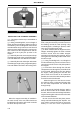
INSTRUCTION MANUAL. Lower wing. Top sid e upper wing Top side low er w ing BALANCING. 1 1) It is critical that your airplane be balanced correctly. Improper balance will cause your plane to lose control and crash. THE CENTER OF GRAVITY IS LOCATED 100-105mm BACK FROM THE LEADING EDGE OF THE WING. Lower wing. 1 2) Mount the wing to the fuselage. Using a couple of pieces of masking tape, place them on the top side of the wing 100-105 mm back from the leading edge, at the fuselage sides. 1 3.
ULTIMATE. *If possible, first attempt to balance the model by changing the position of the receiver battery and receiver. If you are unable to obtain good balance by doing so, then it will be necessary to add weight to the nose or tail to achieve the proper balance point. CONTROL THROWS. 1 1. We highly recommend setting up a plane using the control throws listed. 1 2. The control throws should be measured at the widest point of each control surface. 1 3.
INSTRUCTION MANUAL.