
User Manual


ULTIMATE.
6
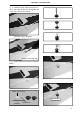
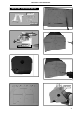
1 4. Locate one nylon servo arm, and using
wire cutters,remove all but one of the arms.
Using a 2mm drill bit, enlarge the third hole
out from the center of the arm to accommodate
the aileron pushrod wire.
1 5. Using pliers, carefully make a 90 degree
bend down at the mark made. Cut off the ex-
cess wire, leaving about 4mm beyond the
bend.
1 6. Insert the 90 degree bend down through
the hole in the servo arm. Install one nylon
snap keeper over the wire to secure it to the
arm. Install the servo arm retaining screw and
remove the masking tape from the aileron.
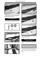
M2 lock nut.
M2 clevis. Snap keeper.
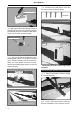
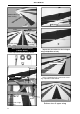
INSTALLING THE AILERON LINKAGES.
1 1. Working with the aileron linkage for
now, thread one nylon clevis onto one of the
threaded wires.
1 2. Attach the clevis to the outer hole in the
control horn. Install a silicone tube on the
clevis.
1 3. Plug the aileron servo into the receiver
and center the servo. Install the servo arm onto
the servo. The servo arm should be
perpendicular to the servo and point toward
the middle of the wing.
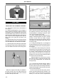
C/A glue.
Repeat the procedure for the right lower
wing half.
bend.
C/A glue.
Bottom of left lower wing