
User manual Tuccano 20cc ARTF A-BH173


SUPER TUCANOINSTRUCTION MANUAL
Item code: BH
173
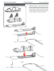
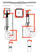
1) It is critical that your airplane be balanced
correctly. Improper balance will cause your plane to
lose control and crash.
THE CENTER OF GRAVITY IS LOCATED 96MM
BACK FROM THE LEADING EDGE OF THE WING.
2) Mount the wing to the fuselage. Using a couple of
pieces of masking tape, place them on the top side of
the wing 96mm back from the leading edge, at the
fuselage sides.
3) Turn the airplane upside down. Place your
fingers on the masking tape and carefully lift the
plane.
4)
AT THE FUSELAGE. BALANCE A PLANE UPSIDE
DOWN WITH THE FUEL TANK EMPTY.
If the nose of the plane falls, the plane is nose
heavy. To correct this first move the battery pack
further back in the fuselage. If this is not possible or
does not correct it, stick small amounts of lead
weight on the fuselage under the horizontal
stabilizer. If the tail of the plane falls, the plane is tail
heavy. To correct this, move the battery and receiver
forward or if this is not possible, stick weight into the
firewall. When balanced correctly, the airplane
should sit level or slightly nose down when you lift it
up with your fingers.
BALANCING
CG
96mm
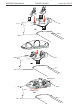
LATERAL BALANCE
After you have balanced a plane on the C.G.
You should laterally balance it. Doing this will
help the airplane track straighter .
1) Turn the airplane upside down. Attach one
loop of heavy string to the engine crankshaft and
one to the tail wheel wire. With the wings level,
carefully lift the airplane by the string. This may
r
e
q
u
i
r
e
t
w
o
p
e
o
p
l
e
t
o
m
a
k
e
i
t
e
a
s
i
e
r
.
2) If one side of the wing fall, that side is heavier
than the opposite. Add small amounts of lead
weight to the bottom side of the lighter wing half's
wing tip. Follow this procedure until the wing stays
level when you lift the airplane.
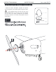
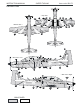
1) We highly recommend setting up a plane using
the control throws listed.
2) The control throws should be measured at the
widest point of each control surface.
3) Check to be sure the control surfaces move in the
correct directions.
CONTROL THROWS
Aileron: mm down
Elevator: mm up mm down
Rudder: mm right mm left
12 mm up 12
8 8
18 18
Flap: 25mm
Low rate:
12mm
Aileron control
12mm
8mm
8mm
Elevator
18mm
18mm
Rudder control
25mm
Flap
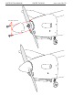
Aileron: 16mm up 16 mm down
Elevator: 14 mm up 14 mm down
Rudder: 30 mm right 30 mm left
High rate:
PRE-FLIGHT CHECK
1) Completely charge your transmitter and
receiver batteries before your first day of flying.
2) Check every bolt and every glue joint in your
plane to ensure that everything is tight and well
bonded.
3) Double check the balance of the airplane.
4) Check the control surface.
5) Check the receiver antenna. It should be fully
extended and not coiled up inside the fuselage.
6
)
P
r
o
p
e
r
l
y
b
a
l
a
n
c
e
t
h
e
p
r
o
p
e
l
l
e
r
.