
Manual
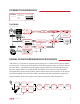


DI/Mic
Switch
Output
Level Pot
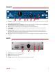
Faceplate
1/4” Input
DI Input
Circuit
Mic Amp
Circuit
Mic Input
Transformer
Backplate
XLR input
Output
Amp
Output
Transformer
Backplate
1/4” Output
CONNECTION DIAGRAMS
LEGEND
Digital Audio
Analog Audio
Data
Clock
TRACKING
Monitor controller/
Multi FX unit
SIGNAL FLOW/HARDWARE BLOCK DIAGRAM
“MIC GAIN” is a 12-position, stepped switch ranging from +12dB minimum gain to +80dB
maximum gain. The majority of the gain for the XLR microphone input comes from the mic
amp gain stage. The signal passes through an input transformer before going to the mic
amp gain stage, which is controlled by the “MIC GAIN” rotary switch on the front panel.
The signal then passes to the DI switch, which selects which input signal (mic or DI) goes to
B173 | User Manual 5