Electrical/EFI Service Manual ATV and Motorcycle P/N : 5002401 August 14, 2002
INTRODUCTION IMPORTANT NOTICE You must possess significant mechanical knowledge, skills, and tools to perform most of the procedures found in this document. This manual is written for Cannondale Motorsports Dealers and qualified service technicians. This is not a comprehensive shop safety manual and should not be used by anyone who is not familiar with standard safety practices and service techniques.
IMPORTANT MANUAL INFORMATION FAILURE TO FOLLOW THE WARNINGS CONTAINED IN THIS MANUAL CAN RESULT IN SERIOUS INJURY OR DEATH. Information important to your safety is distinguished in this manual by the following notations: \ The safety alert symbol means...... “ATTENTION! BECOME ALERT! YOUR SAFETY IS INVOLVED.” DANGER Indicates that DEATH or severe injury WILL result if the instructions are not followed. WARNING Indicates a potential hazard that could result in serious injury or death.
CONTENTS Engine Stop Switch (ATV) Clutch Lever Switch (ATV) Key Switch - - - - - - - Starter Solenoid - - - - Starter Motor - - - - - - Fuses - - - - - - - - - - INTRODUCTION - - - - - - - - - - - - - - - - - - - - - - 3 Important Notice - - - - - - - - - - - - - - - - - - 3 About the manual - - - - - - - - - - - - - - - - - 3 Comments? - - - - - - - - - - - - - - - - - - - - 3 - - - - - - - - - - - - 59 59 59 59 60 60 IMPORTANT MANUAL INFORMATION- - - - - - - - - - - 4 ENGINE MANAGEMENT SYS
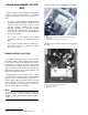
ENGINE MANAGEMENT SYSTEM (EMS) Motorcycle ECUs are located within the subframe. Engine operation is supported by the management system consisting of three main types of electrical components: the ECU, the sensors, and the actuators. • The engine control unit (ECU or ECM) precisely calculates ignition timing and fuel delivery for all engine speeds and loads (based on the currently installed calibration file and its mapping).
ECU PROGRAMMING of the ATV. The ECU is “programmed” with three types of information. the operating code (also known as the “hex” file, the engine calibration file (also known as the “map”), and the vehicle variables or “calibrations.” Calibrations are stored in the map file but are specific to the throttle body and injectors installed on the vehicle. Any programmed information can be changed. using the Cannondale Diagnostic and Maintenance Tool.
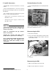
P1 and P2 Connectors Pin identification (P1 or P2) MC1000 ECUs have two main harness connector sockets. Use the following illustration for P1 and P2 pin identification. Remove both main harness connectors from the ECU when performing pin point tests described in this manual. Also, if required, be sure to disconnect any other devices; see the specific pin point tests. • • H G FE D CBA 2 Connector P1 color is black. It connects to the black ECU socket. 4 Connector P2 color is grey.
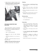
3. Align the latch groove and tab on the ECU socket. Rotate the latch in direction (b) until the latch is locked by the locking tab. The latch should operate freely with your fingers; do not force it. Cleaning 1. Wipe the connector or coupler with a clean, lintfree rag and blow off any moisture using compressed air. 2. Remove corrosion, rust, stains or other foreign material by using contact cleaner on the terminals. 2 3. Apply a water-displacement chemical on connector seals. 4.
BAROMETRIC PRESSURE SENSOR THROTTLE POSITION SENSOR (TPS) The barometric pressure sensor is housed within the ECU. Air pressure within the airbox is transferred to the ECU by a narrow hose. Air pressure information is used to adjust the amount of injected fuel to match the prevailing conditions. The sensor is not user serviceable. If no external problems are found with the hose or the hose routing end points, and a barometric pressure sensor fault persists, the ECU will have to be replaced.
required on a “perfect” throttle body to match the air flow of the vehicle's throttle body at the closed position. Typical values are from 0.0 to 1.0%" starting on page 37. Static Test - Resistance 1 The TPS sensor signal informs the ECU of not only the relative position of the throttle plate, but also the speed with which it is being opened or closed. The engine load is determined by the TPS and engine speed (rpm). The voltage output from the TPS increases proportionately as the throttle is opened.
COOLANT TEMPERATURE SENSOR 1 3. Compare the values. If the two values do not correspond closely, the sensor may be damaged. Go to the next step. 4. Be sure to replace the radiator cap and start the engine and allow to reach operating temperature (60°C). Observe the Engine Temperature (degC) field in the ECU Monitor window. If the value does not increase as the engine warms, go to the next test. Static Test - Resistance 1. Disconnect the sensor harness connector. 1.
2. Compare the value with a reading taken manually in the vicinity of the air temperature tip. If the two values do not correspond closely, the sensor may be damaged. Static Test - Resistance 1. Remove the sensor from the airbox by placing an open-end wrench on the sensor body and turning it counter-clockwise until it can be removed. 2. Measure the sensor resistance between terminals 1 and 2. Refer to "Air Temperature Sensor Resistance Range" starting on page 52.
Static Test - Resistance 1. Disconnect the sensor harness connector. 2. Use an Ohmmeter to measure the sensor resistance between terminals 1 and 2. SERVICE: Crankshaft position sensor resistance range - 532 TO 588 Ohms IDLE AIR CONTROL VALVE (IACV) In a cold engine, the valve opens (arm retracts) allowing more air to bypass the throttle plate. As the engine warms up, the valve closes (arm extends) until the bypass channel through the housing is completely shut at 60°C.
CAUTION : 3. Check the condition of the tip insulator. Make sure it is not cracked, burned, melted, dried out. Do not remove the valve from the housing when performing this test. 4. Make sure the spring is installed with the larger end facing the coil. Dynamic Test - Spark Occurrence 3. Disconnect the engine coolant sensor. 4. Reconnect the idle air control valve to the harness. 5. Press the engine start button quickly without turning over the engine. The valve should extend fully. 6.
On motorcycles, if this relay is damaged, the engine can start but will shut down when the start button is released. number 85. There should be continuity between terminals 30 and 87. If there is not, the relay is damaged; replace it. On ATVs, if this relay is damaged or removed, the engine will run, but damage to a harness diode will result. When the diode fails, the engine will not run. 5.
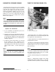
NOTE : When the ignition switch is turned “ON,” the installed relay will make an audible “click.” The fuel pressure regulator maintains the correct fuel pressure in the fuel rail (hoses and injectors). It returns fuel to the tank after fuel passes the fuel injectors. The regulator is connected to the airbox via a small hose. On ATVs the fuel pressure regulator is mounted on the main frame on the right side of the vehicle (front).
and the wiring is in good condition. Make sure the boots are in place. regulator are OK. If the fuel pressure reading is low, quickly disconnect and reconnect the fuel tank return line, if the fuel pressure reading increases when the return line is disconnected, the regulator is faulty replace it. Check for voltage at the pump when the start button is pressed. Check for any open or short circuit conditions in the fuel pump circuit. Consult the vehicle wiring diagram. Take corrective action if necessary.
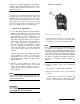
FUEL INJECTORS The fuel injectors are positioned as close as possible to the back of the intake valves. The spray pattern is fixed. The length of time duration that the injectors stay open is calculated by the ECU using the calibration file and data received by the various sensors. 4 3 Dynamic Test - Function NOTE : The following procedure is based on the assumption that there is adequate fuel supply and pressure is available in the fuel rail. 1 2 1. Check the injector wiring harness connectors.
each injector harness connector. Crank the engine over. If the light flashes evenly on each connector, voltage is available at the injectors. 3. If the light fails to flash for either injector, check the fuel injector wiring circuit for continuity. Consult the vehicle’s wiring diagram. Dynamic Test - Operate 1. Disconnect the main harness connector from the cooling fan coupler. WARNING Spinning fan blades can cause the fan to jump on the workbench possibly resulting in severe injury.
CANNONDALE DIAGNOSTIC AND MAINTENANCE TOOL VERSION 2.0 This section of the manual describes how to use the Cannondale Diagnostic and Maintenance software tool. GENERAL INFORMATION 3. Follow the installation screens. When the setup process is complete, the Cannondale Diagnostic and Maintenance program group will be installed and a shortcut to the Cannondale Diagnostic and Maintenance tool will be placed on the your desktop.
In the Windows Explorer, double click the SecurityCode application. Or, you can access this application by clicking on Security code.exe through the program group. HE R E When the DealerCal window displays (see next illustration), call: Optimum Power Technology at 1-800-727-9520 (Monday through Friday, (9 am to 5 pm EST) to obtain the security code needed to activate the software. Electrical_EFI Service Manual.
Enter the Serial provided by the service rep in the DealerCal window. Click Next. ’Device Manager’ Button. 5. Click the ’+’ next to ’Ports’ to expand the available ports detail. If there is a red ’X’ or a yellow ’!’ in front of the Communications Port, a problem exists with your Port Driver. Contact your Computer specialist to resolve the problem. If there is only a connector icon, note the Communications Port Name (COM1, COM3, etc.) Run your DealerCal software.
The vehicle’s lighting or starting electrical systems are isolated from the EMS power relay supplying the ECU. Lighting can remain on if the ECU is powereddown. Or, if insufficient battery voltage is present to hold the EMS relay on, the starter could turn over the engine, but because the ECU is powered-down, the engine would not start. INTERPRETING ERROR MESSAGES Failed to Unlock System 125 Motorcycles 1. Press the ON/OFF button to ON. This will enable the engine management system circuits. 2.
interface cable may be damaged. I/O Error Message 1. You will see this message if the last engine calibration file opened with the software is no longer available such as: if it was deleted or the CD containing it has been removed from the CD drive. OTHER MESSAGES Progress Indicator Whenever data is being transferred between the vehicle ECU and the PC, a progress indicator displays in the upper right area of the main screen. Data transfers should take no more than 1 minute.
Retrying Checksum Data is transferred between the vehicle and PC in small “packets” or chunks. During the transfer process, checks are performed by the diagnostic tool (software) to ensure that the data is not damaged during the transfer. Each small packet is checked during the transfer. If data errors are detected in the packet, the message “Retrying Checksum...” will display in the progress indicator: Typically, this is due to electrical “noise” or other interference during the process.
COMMUNICATION CABLE Connecting the communication cable Motorcycles and ATVs have a “diagnostic” connector integrated into the main wiring harness. The communication cable connects the PC to the vehicle using the connector. CAUTION : Connect the communication cable with the vehicle engine management system OFF. On 2001 and 2002 Motorcycle models, the diagnostic connector is located near the ignition coil at the top of the cylinder head. Vehicle components must be removed to access the connector.
CANNONDALE DIAGNOSTIC AND MAINTENANCE TOOL MAIN WINDOW 1 8 3 9 4 5 6 7 2 1. 2. 3. 4. 5. 6. 7. 8. 9. Numeric Cal ID Description (saved files only - not stored in ECU) Buttons Throttle position sensor min and max values (from vehicle) Throttle Body Leakage (also Throttle Body Offset) (Factory dyno value) Fuel injector flow rate (Factory dyno value) Injector offset (Factory dyno value) Progress indicator Button to access software version information and Cannondale internet files: http://www.cannondale.
Engine Calibration File (“Map”) Identification All Cannondale factory authorized engine calibration files are identified by a Numeric Cal ID code. The Numeric Cal ID number defines the year, model, and issue sequence of any specific engine calibration file. The engine calibration Numeric Cal ID number is displayed in the top left corner of the Cannondale Diagnostic and Maintenance Tool main window whenever a “map” is opened or received from the vehicle ECU.
ATV and Motorcycle operating codes are NOT interchangeable. 2. In the main window click File - Code Download. The software tool can load operating code version updates to the ECU. The software does not read back the installed operating code currently in the ECU.
3. In the ECU Reprogramming Tool window, select the operating code file to send. Have an assistant press and continue to hold the start button. Click Download. The progress indicator will display while the transfer take place. When the transfer is complete release the start button. Click Close. 4. Reinstall the correct engine calibration file. Be sure to update the vehicle variables before sending the file to the ECU. 5. On Motorcycles, be sure to reconnect the starter solenoid.
Opening a SAVED Calibration file CAUTION : NOTE : A saved calibration file might be one that you have received via e-mail, downloaded from the our website, or one that is stored on a diskette or CD. This button functions the same way as if you click File - Open in the top right corner of the main window. Check the Numeric Cal ID field in the main window to make sure the filename selected is displayed. If not, go back to step 2 and repeat.
Receiving a calibration file FROM THE ECU “Reading a map and variables” complete” message. By receiving the engine calibration file or the vehicle variables from the ECU, the technical can determine which specific engine calibration file is in use by the vehicle and what the vehicle specific variable are included in the data file: throttle min/ max, Throttle body leakage (also known as offset, fuel injector flow rate, and injector offset).
Sending a calibration file or “map” to the ECU “Changing a map” You’ll want to pay close attention to what engine calibration file is actually open before you send the file to the ECU in the following steps. Click the OPEN Calibration File (saved) button to open the Open Calibration File window to browse for a saved engine calibration file on your PC. Select the filename and click OPEN.
The throttle position sensor minimum and maximum values must be set using the CDMT anytime the throttle body is serviced (removed, replaced, installed). It also must be set if the ECU operating code is updated. Set the throttle position with the engine off. When the values are set using the tool, the minimum and maximum value actually read into the software by the technician are checked against a range. If any read value is out of range, the software will report it.
to the next step to learn more. Click this butto to read the TP sensor minimu voltage. These fields displays the values that are "ready to accept" The fields initially show a value of the currently open file. The values will change immediately after the buttons at the left are clicked. 7. If you click the Accept Values button, the values of the engine calibration file currently stored in the CDMT will change to the new ones and immediately the Send Calibrations to the ECU prompt will display.
the progress indicator. When the send is complete, the Send complete prompt will display, click OK. Click Cancel and the “From File” values will not be sent. They will remain in the currently open engine calibration file.
at the closed position. Typical values are from 0.0 to 1.0% • “Injector Flow Rate” (Input range 1500 - 3000) Typical values are from 2300-2800 The fuel injectors’ flow rate, used by the ECU to convert fuel mass in milligrams to injector pulse width in milliseconds. The lower the flow rate, the longer the ECU has to hold the injector open to deliver a given fuel mass.
ECU MONITOR 1. Open the Cannondale Diagnostic Tool software on your PC. 2. Power-up the vehicle ECU. 3. Click the MONITOR ECU Parameters button. The ECU monitor window will be displayed. Select “Continuous” to view live data. Select “Hold” to take a snap shot and hold the values displayed. Click CANCEL to exit and close the monitor. ECU Parameters (defined) Monitor selected ECU parameters with the vehicle engine running or with the vehicle engine off and the ECU powered-up.
READING FAULT CODES To read fault codes When a fault is reported, consult the fault diagnostic tables in this manual. Refer to "Fault Troubleshooting" starting on page 42. CAUTION : Obtain the vehicle’s wiring diagram before attempting any testing. NOTE : Most faults reported by the system can be corrected by examining the connector attached to the device or by tracing circuit for an open or short circuit condition between the ECU connectors and the device connector.
ton was pressed. The Fault Report window does not constantly update fault conditions. Fault Report window The Fault Report window sample above was taken while the Cannondale Diagnostic Tool was connected to an 2002 X440s motorcycle. This vehicle does not have a cooling fan. The “Cooling Fan open fault” will report when the tool is connected to a motorcycle, however, it can be disregarded.
FAULT TROUBLESHOOTING Consult the following troubleshooting tables when diagnosing a fault reported by the Cannondale Diagnostic and Maintenance Tool Fault Report window function. Refer to "Reading Fault Codes" starting on page 40. SENSOR SUPPLY VOLTAGE Fault Reported Possible Cause Action ECU damaged Sensor power supply fault Disconnect ECU and go to Test 1. wiring fault Pinpoint Tests Test 1. Check wire and terminal integrity: - P1 B3 2.
SYSTEM VOLTAGE Fault Reported Battery voltage low fault Possible Cause Wiring/ Stator/ Regulator/ Battery Action Check battery voltage at battery; minimum voltage 12.8v. Disconnect ECU and go to Test 1. Battery voltage high fault Ensure regulator output voltage is within specified range. Regulator Pinpoint Tests Test 1. Check wire and terminal integrity: - P2 E1 2. With ignition ‘on,’ check voltage at: - P2 E1 3. Run engine check for presence of fault. Result Action OK Go to Test 2.
FUEL PUMP Reported Fault Possible Cause Action Fuel pump short Damaged fuel pump (internal short circuit), harness short circuit, damaged ECU Fuel pump open Damaged fuel pump (internal open circuit) harness open circuit, harness connector disconnected or terminals at pump loose or disconnected, open circuit to battery 12V(+). Component test fuel pump. Refer to "Fuel Pump" starting on page 44. Make sure fuel pump connector and fuel pump terminals are secure. Verify good main fuse.
IGNITION COIL Fault Coil short fault Possible Cause Damaged ignition coil or ECU, harness short circuit, coil connector disconnected or damaged Action Component test ignition coil. Refer to "Ignition Coil" starting on page 45. Check ignition coil harness connector is secure. Disconnect ECU and go to Test 1. Pinpoint Tests Test Result Action OK Go to Test 2. Faulty Locate and correct and go to Test?. 0.6 Ohms Disconnect ignition coil and go to Test 3. Open circuit Go to Test 4.
COOLING FAN (ATV ONLY) Fault Possible Cause Action Component test the cooling fan. Refer to "Cooling Fan (ATV Only)" starting on page 46. Cooling fan short fault, Cooling fan open fault Damaged cooling fan or ECU, harness short circuit, fan connector disconnected or damaged Component test the coolant sensor. Refer to "Coolant Sensor" starting on page 53. Check that cooling fan harness connector is secure. Verify good main fuse. Disconnect ECU and go to Test 1. Pinpoint Tests Test 1.
FUEL INJECTORS Fault Injector A short fault (left) Injector B short fault (right) Injector A open fault (left) Possible Cause Action Damaged injector or ECU, harness short circuit - flooding indicates short circuit Component test the injector. Refer to "Fuel Injectors" starting on page 19. Damaged injector, injector connector disconnected or damaged, harness open circuit Check that injector harness connector is secure. Disconnect ECU and go to Test 1.
FUEL INJECTORS 3. Check wire for short circuit OK Go to Test 7. - P1 H2 to ground Locate and correct wire fault and go to Test 7. Short circuit - P1 H3 to ground 4. Check wire continuity: Continuity Go to Test 6. Motorcycle Disconnect diagnostic connector CN10, lighting connector CN26, r e m o v e E M S p o w e r r e l a y.
FUEL INJECTORS 5. Check short circuit: OK Go to Test 6. Motorcycle Disconnect diagnostic connector CN10, lighting connector CN26, r e m o v e E M S p o w e r r e l a y. Measure between relay socket terminal 30 and: - P1 H3 - P1 H2 Locate and correct wiring fault proceed to Test 7. Short circuit ATV Disconnect the ignition coil, diagnostic connector CN10, switch engine stop button to OFF position. Measure between P2 E1and: - P1 H3 - P1 H2 6.
THROTTLE POSITION SENSOR (TPS) Fault Throttle position sensor high fault Throttle position sensor low fault Possible Cause Action Component test the TPS sensor. D a m a g e d T P S s e n s o r, ECU, harness short or open circuit, TPS sensor connector disconnected or damaged Check that sensor harness connector is secure. Disconnect ECU and go to Test 1. Pinpoint Tests Test 1. Check wire and terminal integrity: Result Action OK Disconnect TPS sensor and go to Test 2.
AIR TEMPERATURE SENSOR Fault Air temp sensor high fault Air temp sensor low fault Possible Cause Damaged air temperature sensor, ECU, harness short or open circuit, sensor connector disconnected or damaged Action Component test the air temperature sensor. Check that sensor harness connector is secure. Disconnect ECU and go to Test 1. Pinpoint Tests Test 1. Check wire and terminal integrity: - P1 D1 Result Action OK Disconnect TPS sensor and go to Test 2.
AIR TEMPERATURE SENSOR Circuit Diagram Air Temperature Sensor Resistance Range Resistance (ohms) 15071 11739 9215 7290 5808 4659 3763 3058 2500 2056 Temp. (deg. C) Temp. (deg. F) -20 -15 -10 -5 0 5 10 15 20 25 -4 5 14 23 32 41 50 59 68 77 Resistance (ohms) 1700 1414 1181 992 837 710 604 517 444 382 Electrical_EFI Service Manual.fm © 2002 Cannondale Corporation - All Rights Reserved Temp. (deg. C) Temp. (deg.
COOLANT SENSOR Fault Reported Engine temp sensor high fault Engine temp sensor hi fault Possible Cause Damaged coolant temperature sensor, ECU, harness short or open circuit, sensor connector disconnected or damaged Action Component test the coolant temperature sensor. Refer to "Coolant Sensor" starting on page 53. Check that sensor harness connector is secure. Disconnect ECU and go to Test 1. Pinpoint Tests Test 1. Check wire and terminal integrity: - P1 B2 - P1 E4 2.
Coolant Sensor Resistance Range Resistance (ohms) 45313 34281 26114 20003 15462 12002 9397 7415 5896 4712 3792 3069 Temp. (deg. C) -40 -35 -30 -25 -20 -15 -10 -5 0 5 10 15 Temp. (deg. F) -40 -31 -22 -13 -4 5 14 23 32 41 50 59 Resistance (ohms) 2500 2057 1707 1412 1175 988 834 703 595 508 436 374 Electrical_EFI Service Manual.fm © 2002 Cannondale Corporation - All Rights Reserved Temp. (deg. C) 20 25 30 35 40 45 50 55 60 65 70 75 Temp. (deg.
IDLE AIR CONTROL VALVE (IACV) Fault Reported Stepper motor fault Possible Cause Damaged idle air control valve, ECU, harness short or open circuit, IACV connector disconnected or damaged Action Component test the IACV. Refer to "Idle Air Control Valve (IACV)" starting on page 55. Check that harness connector is secure. Disconnect ECU and go to Test 1. Pinpoint Tests Test 1. Check wire and terminal integrity: - P1 E1 - P1 E2 - P1 F1 - P1 F2 Result Action OK Go to Test 2.
CRANKSHAFT POSITION SENSOR Fault Reported Possible Cause Action Check that harness connector is secure. Crank tooth sync fault Damaged or contaminated crankshaft position sensor, damaged ECU, harness short or open circuit, IACV connector disconnected or damaged Check sensor air gap: 0.5 to 1.0 mm Check for damaged flywheel teeth. Check flywheel runout or play. Disconnect ECU and go to Test 1. Pinpoint Tests Test Result Action 1.
COMPONENT TESTING (NON-EFI) Test for continuity between both black wires; there should be continuity. BATTERY Test for continuity between both red wires; there should be continuity. 1. Filling electrolyte properly, Charging (times and rates). Test for short circuit between one of the red wires and the two blacks; there should be no continuity. Repeat the test for the other red wire. There should be no continuity. 2. Load testing using a commercially available load tester. 3. Installation 4.
If an OL (no continuity) is obtained on any one of the three tests, replace the rectifier/regulator. Stator NOTE : If vehicle is equipped with a single phase stator, complete the steps described, but omit the references made to the third wire (three phase stator). Static Test 1. Disconnect the stator connector. 2. Set multi meter to the lowest Ohms setting. Measure the resistance between all three wires coming from the stator. Start with one wire and read resistance between it and the other two.
ENGINE STOP SWITCH (ATV) STARTER SOLENOID 1. Disconnect the engine stop switch from the main harness. Dynamic Test - Solenoid Function 2. Slide the switch to the RUN position. There should be continuity between the two switch leads. 1. Press the engine start button. On ATVs, the additional step of turning the ignition key ON and pulling in the clutch lever is required before pressing the start button. 3. Slide the switch to the OFF position. There should be no continuity.
Operation Test harness starting circuits for short or open circuits. Consult the vehicle wiring diagram. 1. Disconnect the solenoid from the main wiring harness. If the starter motor does not turn, confirm that the engine can be turned over manually. If the engine does not turn over manually, there is a internal engine problem. Take corrective action. 2.
Starter Solenoid - - - - - - - - - - - - - - - - - 59 Starter Motor - - - - - - - - - - - - - - - - - - - 60 Fuses - - - - - - - - - - - - - - - - - - - - - - 60 INTRODUCTION - - - - - - - - - - - - - - - - - - - - - - 3 Important Notice - - - - - - - - - - - - - - - - - - 3 About the manual - - - - - - - - - - - - - - - - - 3 Comments? - - - - - - - - - - - - - - - - - - - - 3 IMPORTANT MANUAL INFORMATION- - - - - - - - - - - 4 ENGINE MANAGEMENT SYSTEM (EMS) - - - - - - - - - 6 Engine Control Unit (ECU)