
Service manual


© 2002 Cannondale Corporation - All Rights Reserved
8
Electrical_EFI Service Manual.fm
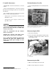
P1 and P2 Connectors
MC1000 ECUs have two main harness connector
sockets.
Remove both main harness connectors from the
ECU when performing pin point tests described in
this manual.
Also, if required, be sure to disconnect any other
devices; see the specific pin point tests.
• Connector P1 color is black. It connects to the
black ECU socket.
• Connector P2 color is grey. It connects to the
grey ECU socket.
CAUTION:
Allow connector rotating latch to draw the
connector into the ECU socket (coupler). Do not
press or force the connector; it should slide
into the socket easily.
Check for contamination and pin condition
before reconnecting.
Lubricate the connector seals with a high-
quality dielectric grease before reinstalling.
Use a commercially available pin gauge when
performing pin point tests. Ordinary tester
probes can spread pins resulting in loose
connections.
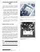
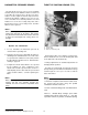
Pin identification (P1 or P2)
Use the following illustration for P1 and P2 pin iden-
tification.
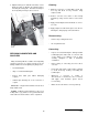
Disconnecting the ECU
1. Disconnect the battery.
2. Press in the latch locking tab and rotate the latch
in direction (a) until it stops. Pull the connector
from the ECU socket.
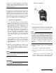
Reconnecting the ECU
1. Make sure the battery is disconnected.
2. Make sure the main fuse is removed.
This photo shows how to identify individual pins in the ECU
harness connectors. Each row is identified by a number 1-4.
Each column is identified by a letter A - H.
1. Latch
2. Locking tab
H
H
B
G
F
E
D
A
C
H
B
G
F
E
D
A
C
1
2
3
4
a
1
1