
Installation manual

BEFORE INSTALLING THE SYTEM
• DO read through this installation manual.
• DO NOT install the alarm brain in an engine compartment.
• The alarm may arm itself when power is first connected.This is a normal condition.
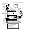
ITEMS SUPPLIED WITH THE SYSTEM
Receiver and Control Module Valet/Override Switch
2-Button, Code Learning LED Status Indicator
Transmitters (2) Wiring Harness, Fuseholder, & Fuse
Six-tone, soft chirp, 120 dB Siren Dual Zone Electronic Shock Sensor
Door Lock Harness
OPTIONAL ACCESSORIES
Radar Field Sensor..............................................MAS-2 Backup Battery........................................................BWS-500
Window Roll up................................................WRM-2 Remote Starter .......................................................RAS-101
Power Door Lock.............................................PDL-50 Trunk Release..............................................................TR-100
Relay...........................................................................SPDT Starter Disable Relay Socket................................BRS-003
5-wire Door Lock relay & socket ...BRS-008P16 Glass Sensor.........................................................BWS-200P
(+) Door Lock Inverter........................BW-345P16
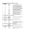
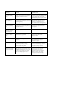
SPECIFICATIONS
Operating voltage..................+12 VDC Neg. Ground
Code Learning ........................................3 Codes Max.
Current consumption............5 mA (max) disarmed.
Siren output drive........................................3 Amperes
Automatic reset..........................................60 seconds.
Door Lock/Unlock Output......................(-) 500 mA.
Horn Output................................................(-) 250 mA
Dome Light Output....................................(-) 250 mA
Channel 2 Output Drive.....................(-) 500 mA variable.
Channel 3 Output Drive.........................................(-) 500 mA
Remote control transmit frequency.......................310 mHz.
Passive arming delay..................................30 Seconds approx.
Auxiliary output drive...............................250 mA maximum.
Flashing output drive..................................10 Amp maximum.
Trigger inputs ...................................................1) Neg. Pnswtch.
1) Pos. pnswtch. 1) Neg. sensor or aux. pnswtch.
SECURITY
SYSTEM
INSTALLATION MANUAL