H.264 Network IP Camera User Manual Product: BLK-IPS103 Please read this manual before using your camera, and always follow the instructions for safety and proper use. Save this manual for future reference.
WARNING RISK OF ELECTRIC SHOCK. DO NOT OPEN. To reduce the risk of electric shock, do not remove cover (or back). No user serviceable parts inside. Refer servicing to qualified service personnel. CAUTION Operate this camera only in environments where the temperature or humidity is within the recommended range. Operation in extreme temperatures or humidity levels may cause electric shock and shorten the life of the product.
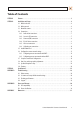
Table of Contents SECTION 1 SECTION 2 SECTION 3 APPENDIX A APPENDIX B APPENDIX C Features. . . . . . . . . . . . . . . . . . . . . . . . . . . . . . . . . . . . . . . . . . . . . . . . . . . . . . . . . . . . . . . . . . . . . . . . . . . . 2 Installation and Setup. . . . . . . . . . . . . . . . . . . . . . . . . . . . . . . . . . . . . . . . . . . . . . . . . . . . . . . . . . . . . . . . 4 2.1 What’s in the box . . . . . . . . . . . . . . . . . . . . . . . . . . . . . . . . . . . . . . . . . . . . . .
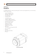
SECTION 1: FEATURES SECTION 1 Features The DIGIOP Black BLK-IPS103 is a professional, premium-grade, CS-mount box camera designed for indoor use. Lens and mounting bracket are optional. It features: • • • • • • • • • • • • • • • • • • • Sony® 1/3” Super HAD CCD sensor High Quality SS-HQ1 full kit chip set True Day/Night (ICR) and WDR Dual streaming mode De-interlacing on DSP Unicast/multicast support H.264/MPEG-4/MJPEG, 25/30 fps @ D1 G.
SECTION 1: FEATURES Reset USB Analog video out DC jack adapter cable connector 9-pin terminal block Micro SD card slot LAN 4-pin connector for Auto Iris Back connectors and controls Reset – For restarting the camera, or resetting the camera to its factory default network settings. See Appendix A, Troubleshooting, for more information. USB mini-B connector – For a USB storage device or Wi-Fi networking device. Power adaptor connector (DC 12V) – For use with the DC jack adapter and DC12V power adapter.
SECTION 1: INSTALLATION AND SETUP SECTION 2 Installation and Setup 2.1 What’s in the box Your camera includes the following: • • • • • • • • • • BLK-IPS103 camera body Mounting ring Cap for protecting the CCD DC power adapter with power plugs for different powering sources DC jack adapter cable 9-pin terminal block Quick installation guide Mounting adapter and screws for attaching the camera to a mounting bracket Hex wrench CD mini disk with application software and documentation 2.
SECTION 2: INSTALLATION AND SETUP 2. Install the camera mounting bracket using the instructions provided with the bracket. 3. Attach the adapter for mounting the camera to side with the label or to the opposite side with the screws provided. Mounting adapter 4. Remove the protective cap covering the camera CCD. 5. Attach the lens assembly to the camera by screwing it clockwise onto the camera until it is fully seated. The lens may require a mounting ring adapter to fit onto the camera.
SECTION 2: INSTALLATION AND SETUP 7. If the lens assembly has an Auto Iris feature, attach the lens cable to the 4-pin connector on the back of the camera. Pin definitions are shown in the table below. 8. Attach the camera to the mounting bracket. Use the instructions provided with the bracket. 9. Remove the protective cap from the end of the camera lens, if one is attached. 2.
SECTION 2: INSTALLATION AND SETUP 2.4.1 Audio in/out connections The camera includes an interface for a mono audio input (from a microphone) and a mono audio output (to a speaker). The audio output is a low level signal that requires an amplified speaker (see Specifications). The configuration of the audio wiring (Aout, Ain) is shown in the following diagram.
SECTION 2: INSTALLATION AND SETUP Voltage type sensor wiring schematic Relay type sensor wiring schematic To connect a sensor to the camera, strip 1/4” of insulation from the sensor wires and insert them into the terminal block in the DI pin locations shown above. The pin marked “C” in the terminal block is the common (COM) pin. 2.4.3 Alarm out (DO) connection The camera supports one alarm out connection to relay type device. It provides up to 24 VAC @ 500 mA or 12 V DC @ 1 A.
SECTION 2: INSTALLATION AND SETUP Relay type alarm wiring schematic To connect an alarm reporting device to the camera, strip 1/4” of insulation from the alarm wires and insert them into the terminal block in the DO pin locations shown above. The pin marked “C” is the common (COM) pin. 2.4.4 RS-485 device connection The camera provides one RS-485 interface connection. The wiring signal polarity to the connector block is shown in the schematic below.
SECTION 2: INSTALLATION AND SETUP 2.4.6 LAN and power connections Your camera can be powered locally with a 12 V DC adapter or with Power over Ethernet (PoE, see Appendix B). If you are using PoE, you do not need to attach a power adapter to the camera. 1. Attach a LAN cable to the Ethernet connector on the back of the camera. If your camera will be powered through the LAN cable, DO NOT apply power to your camera at this time. 2.
SECTION 2: INSTALLATION AND SETUP The IPAdminTool can be loaded on a Microsoft Windows XP, Vista or Windows 7 operating system (32- or 64-bit). To use this utility for the initial setup of your camera, your computer must be connected to the same network subnet as your camera. At a computer on the same LAN (subnet) where your cameras will be installed, do the following: 1. Insert the CD mini disk provided with your camera into your computer’s CD ROM drive and open the CD in a Windows Explorer window. 2.
SECTION 2: INSTALLATION AND SETUP 2.6.1 Configuring cameras on networks with DHCP In networks with a DHCP server, the IP camera will acquire dynamic (changeable) network settings when it is initially powered on. These dynamic settings can easily be converted to static settings, or changed to other static settings that are also compatible with your network. 1. Connect your camera to the LAN, then power on the camera. 2.
SECTION 2: INSTALLATION AND SETUP 4. In the IP Setup window, click the Static option bullet to select this option. Static Option If you have other compatible, network settings you want to apply to the device, enter them in the appropriate locations. Click Setup to save settings. 5. In the Login window, enter the ID and PW (password) for your camera and click Login. The default administrator values for the ID and PW are root and pass. After entering ID and PW, the IP Setup window closes. 6.
SECTION 2: INSTALLATION AND SETUP —— —— —— Check the network for compatibility with the default static network settings of your camera. Find network settings (IP addresses) that are not in use and can be assigned to your camera. Attach your camera to the network, power it on, and configuring it with new network settings. Determine the network settings of your computer 1.
SECTION 2: INSTALLATION AND SETUP Table 1. PC/Camera network settings Computer (PC) Camera IP Address Subnet Mask Default Gateway CAUTION If connecting your camera to an enterprise network, consult with your network administrator for the camera IP address, subnet mask, and default gateway. Find network settings (IP addresses) that are not in use 1. At your PC, find an IP address on your network that is not in use: a. Write down the EXACT IP address of your PC up to the third/last period.
SECTION 2: INSTALLATION AND SETUP In the example shown above, the message “Reply from 192.168.1.200: ..” indicates that your PC can reach the device with that IP address, and that address is in use (i.e., you cannot use it for your camera). d. Since the ping test of the IP address we tried showed the address was in use, try another number between 1 and 254. For example, let’s ping 192.168.1.201. At the DOS prompt, enter: ping 192.168.1.201 e.
SECTION 2: INSTALLATION AND SETUP Configure the camera IP address 1. Open the IPAdminTool directory on your computer, then double click the file IPAdminTool.exe to start the application. When the IPAdmin Tool starts, it will discover all the IP devices it supports that exist on the network. The discovery process may take a few minutes. 2. In the Product list, find the entry with the same MAC address as the camera you installed. If the camera is not shown, click Refresh once a minute to update the list.
SECTION 2: INSTALLATION AND SETUP Click SETUP. A Login window will open. d. 5. In the Login window, enter the ID and PW (password) for your camera, then click Login. The default administrator ID and PW are root and pass. After entering the ID and PW, the IP Setup window closes. 6. In the IPAdmin Tool window, click Refresh and verify that the entry representing the camera now shows the new IP address. 7.
SECTION 2: INSTALLATION AND SETUP Typical initial camera view NOTE 4. If, after logging into your camera, you cannot see live video and the message: “Can not Create XMLDOMDocument Install MSXML4.0” appears, download and install the MS XML 4.0 library. This library can be found at: http://www.microsoft.com/downloads/details.aspx?familyid=3144B72B-B4F2-46DA-B4B6-C5D7485F2B42&displaylang=en In the camera window, click the SETUP link in the upper right corner of the window.
SECTION 2: INSTALLATION AND SETUP 5. 6. 20 Under the Basic Configuration menu, click Date & Time. In the Date & Time Setting options: a. Select the Time Zone you prefer. b. Select the synchronization method, or select Set Manually and enter the appropriate information. c. Select the Sync Source and Interval you prefer. d. Click Apply. In the Basic Configuration menu, click Users. www.digiop.
SECTION 2: INSTALLATION AND SETUP 7. In the User List, click root, and then click Modify and follow the prompts. Setup the administrator user with a new password and click OK. 8. In the Users menu, click Apply, then click OK to restart the web server (if you wish to do so at this time). 9. Click Add to include other administrators, operators or viewers to the user list. Follow the screen prompts to complete the entries. 10.
SECTION 2: INSTALLATION AND SETUP 1. From the View window, click: SETUP > Video & Audio > Video-In 2. Scroll to the bottom of the screen and click the PREVIEW button. Follow the screen instructions to open the camera view in another IE window. 3. While observing the video in the PREVIEW window, adjust the values for brightness, contrast, hue, saturation, sharpness, and/or other parameters on screen. Click Apply to see the effect of the change.
SECTION 2: INSTALLATION AND SETUP 2. In the Bi-directional Audio Settings menu, click the checkboxes to select “Listen to the audio from server with setting below” and “Talk to the speakers of server”. 3. Click Apply, and then click VIEW to return to the camera view screen. 4. On the VIEW screen, check the SPK and MIC options to enable the speaker at the camera and the microphone on your computer. 5. At your computer, listen for sounds from the microphone at the camera.
SECTION 2: INSTALLATION AND SETUP 2.10 Cleaning Clean the camera housing with an approved glass cleaning solution and a lint free cloth. • • Dust can be removed from the unit by wiping it with a soft damp cloth. To remove stains, gently rub the surface with a soft cloth moistened with a mild detergent solution, then rinse and dry it with a soft cloth. Remove all foreign particles, such as plastic or rubber materials, attached to the camera housing. These may cause damage to the surface over time.
SECTION 3: SPECIFICATIONS SECTION 3 Specifications Table 2. Specifications Camera Module CCD Sync ELECTRICAL Image Sensor SONY 1/3” Super HAD CCD Effective Pixels NTSC: 768(H) x 494(V); PAL: 752(H) x 582(V) Scanning system 2:1 interlace Size 1/3 inch interline transfer CCD Frequency NTSC: 15.734 KHz (H) 59.94 Hz(V); PAL:15.625 KHz(H) 50.00 Hz (V) Resolution 550 TV lines S/N (Y signal) 52 dB (AGC off, weight on) Min. Illumination 0.00001 Lux/F1.
SECTION 3: SPECIFICATIONS Function Digital Input/output 1/1 channel RS-485 Supported Network 10/100Base-T Power over Ethernet Supported Protocol TCP/IP, UDP/IP, HTTP, RTSP, RTCP, RTP/UDP, RTP/TCP, SNTP, mDNS, UPnP, SMTP, SOCK, IGMP, DHCP, FTP, DDNS, SSL v2/v3, IEEE 802.1X, SSH USB 2.0 Supported – mini-B plug SD Slot Supported – MicroSD (MicroSD card not included) Electrical characteristics Video Output 1 Vp-p, 75Ω Audio Input Line-in, 1.43 Vp-p (min 1.35 Vp-p, max 1.
APPENDIX A: TROUBLESHOOTING APPENDIX A Troubleshooting A.1 Reboot camera NOTE The reboot process lasts about 2 minutes, during which time the camera will not respond to the IPAdmin Tool or transmit video to a web browser The camera can be rebooted in two ways: • • Using the IPAdmin Tool: a. Start the IPAdmin Tool. b. Find the entry for the camera you want to reboot and click it to select (highlight) it. c. Click the Reboot button and enter the administrator ID and PW. d.
APPENDIX A: TROUBLESHOOTING To force the camera to the factory network settings: 1. Disconnect the power (adapter) from the camera. 2. While pressing and holding down the reset button, power on the camera. 3. Release the Reset button 5 seconds after applying power. 4. Wait for the camera to reboot. A.3 Checking your Firmware Firmware is software embedded in the camera that determines many of its features and functionality.
APPENDIX B: POWER OVER ETHERNET APPENDIX B Power over Ethernet The BLK-IPS103 camera supports Power over Ethernet (PoE) in conformance with the IEEE 802.3af standard. IEEE 802.3af allows for two power options for Category 5 cables. The PoE module signature and control circuit provides the PoE compatibility signature and power classification required by the Power Sourcing Equipment (PSE) before applying up to 15 W power to the port.
APPENDIX C: DIMENSIONS APPENDIX C Dimensions .55” 30 www.digiop.com 1.02” 1.48” .