BLK-PTZJOY3 3-Axis Joystick Controller INSTRUCTION MANUAL BLK-PTZJOY3
SYSTEM CONTROLLER WARNING TO REDUCE THE RISK OF FIRE OR ELECTRIC SHOCK, DO NOT EXPOSE THIS PRODUCT TO RAIN OR MOISTURE. DO NOT INSERT ANY METALLIC OBJECTS THROUGH THE VENTILATION GRILLS OR OTHER OPENINGS ON THE EQUIPMENT. The lightning flash with arrowhead symbol, within an equilateral triangle, is intended To alert the user to the presence of un-insulated "dangerous voltage" within the product's enclosure that may be of sufficient magnitude to constitute a risk of electric shock to persons.
SYSTEM CONTROLLER CONTENTS General Descriptions, Features ...……..………………………..…. 5 Installation ...................……………….....………………….…..……. 6 Part names & Functions …………………...………….…….……..…. 7 Display LCD window ……………………....………………….......….. 8 PTZ Control ....................…..….……………....…...……....….…… 9 PTZ Configuration ..........…..….……………....…...……....….…… 11 Hidden command …………………………………....………….…….. 12 Specifications & Dimensions ……...………....……………………….
SYSTEM CONTROLLER General Descriptions The BLK-PTZJOY3 is a pan/tilt controller that allows operators to perform the following functions : • Controls camera functions such as pan, tilt, zoom, and focus. • Sets and calls camera preset positions • Activates pre-programmed group presets, tour and group sequences. The LCD is used to display current status as well as to provide a menu system for setting operational parameters.
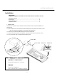
SYSTEM CONTROLLER Installation UNPACKING Unpack the equipment and make sure all listed items are included in the box. Keyboard controller ………………………………………………….……… 1 Junction box ………………………………………………………….………. 2 3m 6p cable RJ-11………………………………………………….………… 2 Instruction manual ….………….…………………………………………….. 1 1. CONNECTIONS There are two connectors on the controller. These connectors are RJ connector for Master and Slave control. 1.
SYSTEM CONTROLLER Parts name & functions 3 4 5 2 1 19 20 21 15 16 17 18 22 6 7 8 9 10 11 12 13 14 1. LCD Display : Displays numeric input, system status, function status, general status, etc. 2. Shows the communication status (Master / Slave) 3. Mon : Select output channel of Matrix Switcher. (TBD) 4. Quad : Select channel of Quad.(TBD) 5. Mux : Select channel of Mux.(TBD) 6. 0~9 :Numeric keypad : 7. CLR : Cancel key . 8. CAM : Select address of Camera, Mux, Quad and Matrix Switcher. 9.
SYSTEM CONTROLLER Parts name & functions 1 2 1. Slave Port : Connect to Slave Communication Port. 2. Master Port : Connect to Master Communication Port Drawing of Console Desk BLK-PTZJOY3 is designed to use on the console desk. When you install the keyboard on the console desk, please make holes as below drawing.
SYSTEM CONTROLLER Display LCD window (1) Initial display PROTOCOL PELCO-D : 2400 BPS PTZ ADDR 001 MON CHAN 001 PRE GRO TOUR SCAN PATT FOCUS 1. C-001 : Shows the current camera No. (Address). 2. M-001 : Displays output channel of Matrix Switcher. (TBD) 3. DRX5 : Shows the selected camera protocol. 4. Func : Displays entered Key.
SYSTEM CONTROLLER • Control and Setting of PTZ Camera Functions 1. Setting to the camera functions ① Camera Setting Menu 1 Camera Address Press MENU button Each menu page is provided with a highlighted cursor which can be moved around the page using the Up, Down, Left and Right cursor keys with Joystick. ** Note: Dome camera menu is different according to camera manufacturers.
SYSTEM CONTROLLER • System Controller (Keyboard) Functions setting 1. System functions setting PTZ Camera (Rx) and Protocol setting. ① 1 ② You will be prompted for a password if one has previously been set (factory default is “0000”.) ③ Set the information as LCD show you by using joystick. ④ PTZ Configuration is as below.
SYSTEM CONTROLLER PROTOCOL PELCO PTZ ADDR 001 MON CHAN -D : 2400 BPS Accessing the system setup menu Pressing keypad 1 and then holding the SET key for approximately 2 seconds. It provides access to the system setup menu system. 001 PRE GRO TOUR SCAN PATT FOCUS ZOOM Note: You will be prompted for a password if one has previously been set (factory default is “0000”) PASSWORD? NO. : Select camera address to be changed. 1. NO. 001 2. TYPE PTZ TYPE : Select camera type. 3.
SYSTEM CONTROLLER 2.Hidden command This hidden menu performs to operator to change PASSWORD and others. ① 2 SET ② You will be prompted for a password if one has previously been set (factory default is “0000”.) ③ Set the information as LCD show you by using joystick. ④ PTZ Configuration is as below.
SYSTEM CONTROLLER Model BLK-PTZJOY3 Pan/Tilt interface: RS-485 DVR interface: RS-485 Keyboard Communication Pan/Tilt operating distance: 4000 ft (1029m) on 24 AWG wire Protocol: Multiple ( Wonwoo, etc. ) (Baud rate selectable) Connector Type Data Keyboard Keypad RJ-11 6-pin modular PC Keyboard button Numeric keyp ad and camera function ke ys. Joystick Three-axis, vector solving, with twisting, return-to-center head Input Voltage 12 VDC ± 2V Power Consumption Max.