
Installation Manual
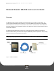

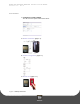
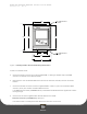
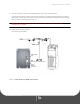
Table Of Contents
- Heading - Vending Reader VR4100 Installation Guide
- Heading1 - Overview
- Heading1 - Reader Installation
- Heading1 - Reader Configuration
- Heading1 - Reader Test
- Heading1 - Reader Audit
- Heading1 - Reader Factory Default Settings
- Heading1 - Reader Specifications

V ENDING READER VR4100 INSTALLATION GUIDE
D OCUMENT 1277 REV 02
PRINTED O CTOBER 19, 2010 5
Figure 3: Vending Reader Face and Mounting Dimensions
C
ONNECT THE READER CABLES
5 Connect the single connector end of the supplied MDB 'Y' cable (p/n 055-800-132) to the MDB
connector on the back of the VR4100 reader.
6 Disconnect the coin mechanism MDB connector from the machine controller; note the connection
location.
7 Connect the double connector end of the supplied MDB 'Y' cable to a.) the coin mechanism MDB
connector, and b.) the machine controller MDB connector.
A 16' MDB extension cable (VE/MDBDPCE16) is available from Blackboard if the supplied 30" cable is
not long enough.
8 Connect one end of the supplied CAT5 network cable into the reader:
Ethernet connection (10/100Base-T): 'NET' port
The network cable is a CAT5 patch cable with RJ45 connectors on each end.
3.10”
2”
4.6”
.250” DIAMETER SLOT
2 PLACES
.200” DIAMETER SLOT
2 PLACES
4.23”
5.20”
3.33”
3.70”