
User's Manual

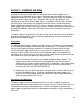


Battery Installation Procedure:
1. Place the batteries on the lower shelf of the enclosure, positive terminal facing out.
2. Route the terminal connector ends of the battery cable from the power supply
compartment at the top of the enclosure to the battery compartment.
3. Wire the batteries in series, connecting negative post of one battery to positive
post of the next. Battery cables and terminals are color coded to aid in correct
wiring. Black terminal is negative (-); red terminal is positive(+).
4. After completing all connections to the battery terminals, use a digital multimeter
(DMM) to verify proper voltage and polarity at the battery cable connector that
terminates to the power supply DC input port. For 3-battery systems, indicated
voltage should be approximately 36 volts or slightly higher. In a 4-battery system,
indicated voltage should be approximately 48 volts or slightly higher. When the
red and black meter probes are connected to the corresponding colored terminals
of the battery harness connector, the meter should indicate positive (+) voltage,
assuming proper connections at the meter itself.
WARNING
If voltage and polarity indications do not correspond to those
described above, determine the cause before mating the battery
connector to the power supply. Incorrectly wired batteries can cause
personal injury or permanent damage to equipment.
5. Space the batteries approximately 1 inch apart to provide adequate airflow.
6. Attach the body of the temperature sensor probe to the side of the center battery
using self-adhesive tape rated for use in wide temperature ranges. Depending
upon battery construction, it may be necessary to hang the sensor in close
proximity to the side of the battery instead of attaching it directly.
19