
User's Manual


General Installation Procedure: Ground Mounted Cabinet
The following procedure is intended as a general guideline only for ground-mounting a
cabinet on a pad or pedestal. Actual mounting methods used will be dictated by local
codes and requirements. All local codes and standards for construction techniques must
be observed when planning and executing a cabinet installation.
The following requirements should be noted before commencing installation activities:
Obtain any and all necessary permits and easements before pouring any concrete or
installing the cabinet. Permission to mount the UPS shall be obtained in accordance with
agreements between the cable company, the utility company, and any government entity or
body having jurisdiction.
INSTALLATION NOTE: Tighten all mounting hardware securely before installing the UPS
and batteries into the cabinet. Failure to do so may result in the cabinet flipping over
and causing severe injury to the installer.
For maximum strength and security, use a poured-concrete pad. The mounting bolts should
be 7/16-inch in diameter and cast in the concrete whenever possible. Make a suitable
template of the pedestal skirt for mounting bolt placement.
Local codes may require that a service disconnect switch equipped with overcurrent
protection be installed between the power supply and the utility. The utility power
conductors shall be connected to the power supply through an appropriate service entrance
equipment.
1. Be certain the intended mounting surface, either poured concrete or pre-cast, is level and
square and that all necessary power and coaxial connections are stubbed up correctly.
2. Install the cabinet over the mounting bolts and secure to the pad with the appropriate
hardware. Tighten all hardware securely.
3. Connect electrical wiring in the service entrance box as necessary. Observe all national and
local electrical codes. A licensed electrician must perform this step, and the proper
authorities must inspect the resulting work.
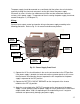
4. Connect the CATV power feed coax to the output fitting on the cabinet. This connector may
be internal to the cabinet depending on the installation. In some cases it will be necessary
to terminate the coax with a pin type connector with the “stinger” (inner conductor of the
hard line) trimmed to ½- inch beyond the threaded portion of the connector body. A right
angle connector may be required, depending on specific installation conditions at the site.
13