
User's Manual


Section 6: Startup and Operation
The power supply is ready to be placed into operation after it has been installed in its
enclosure and all input and output connections have been made,. Ensure that AC input
power is available to the power supply receptacle then perform the following steps in
sequence.
CAUTION
The following steps in the startup procedure MUST be performed exactly
as presented; otherwise, permanent damage to the power supply may
result. Observe the status of the LED indicators as a guide in performing
the startup procedure.
1. Ensure that the BATTERY CIRCUIT BREAKER has been operated to the OFF (0)
position. All connections and initial wiring must be in place as previously outlined
and described.
2. Operate the utility AC circuit breaker in the service entrance box to the ON position.
The power supply should start and immediately begin delivering power to the load.
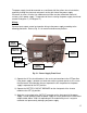
3. The LINE and SENSOR indicators should be illuminated green before proceeding.
The BATTERY indicator will illuminate red before the battery circuit breaker is
closed. The BATTERY CIRCUIT BREAKER on the front panel of the power supply
may be placed to the ON (1) position only after verifying that the LINE and SENSOR
indicators are illuminated green.
4. The BATTERY indicator should change from red to green after the BATTERY
CIRCUIT BREAKER is turned ON. Following a short time delay and with AC line
voltage within acceptable limits, the BATTERY indicator should change from green
to amber. This occurs when the internal battery charger begins delivering a high
rate charge to the external batteries. High rate charge will end automatically and is
signalled when the BATTERY indicator changes color from amber to green.
5. The power supply is now operating in its normal mode. All indicators on the front
panel of the power supply should be illuminated green, perhaps with the exception of
the CHARGER indicator which may be amber. Additionally, the TEST indicator
should either be extinguished or may flash amber occasionally as the status monitor
circuits communicate with the external transponder, if connected.
20