
User's Manual

DANGER
Performing the following procedure exposes the servicing technician to
hazardous voltages and will disrupt power to the system loads. The
servicing technician MUST verify that AC and DC input sources to the
power supply have been removed. If system power must be maintained
during input voltage reconfiguration, connect the output from a service
supply to the power insertion point of the cable before proceeding.
1. Perform Steps 1) and 2) of the shutdown procedure appearing in Section 7) of this
manual.
2. If necessary, ensure that power to the cable system is being provided by a service
supply. Verify that the AC input cord of the power supply has been disconnected
from its receptacle.
3. Disconnect the output cable from the power supply, then remove the left-side front
panel. Retain all mounting hardware.
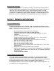
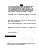
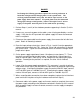
4. Place the input voltage select wires shown in Fig. 9-1 and 9-2 into the appropriate
voltage connection terminal of TB1. Select the 120 or 240-volt position as required
per system needs. Tighten the terminal board screws to secure the voltage select
jumper wire in place.
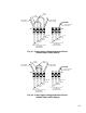
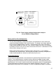
5. On the power supply output board, locate J10 adjacent to transformer T1. These
terminals are configured by two pin jumpers: one position for 120-volt input; the
other for 240-volt input. Refer to Fig. 9-3 for a diagram of the required pin jumper
positions. Reconfigure the positions as required, for either 120- or 240-volt
operation.
6. Locate J5 on the power supply output board. This connector is used for inserting a
metal-oxide varistor (MOV) into the power line input circuit for protection against high
voltage surges. If configuring the power supply for nominal 240 VAC input, connect
a 275 volt MOV (part no. 160-006-10) to J5. If configuring the power supply for
nominal 120 volt input, connect a 130 volt MOV (part no. 160-002-10) to J5.
7. When reconfiguration connections have been completed, replace the left-side front
panel and fasten into place using the hardware retained from Step 3).
8. Reconnect cables to the power supply and inverter module as required, then restart
the power supply according to the procedure contained in Section 6) of this manual.
After the power supply has been restarted, remove the service supply to complete
this procedure.
26