Installation and Operation Manual Cintel Scanner May 2020 English, 日本語, Français, Deutsch, Español, 中文, 한국어, Русский, Italiano, Português and Türkçe.
English Welcome Thanks for purchasing your new Cintel scanner! Your new scanner runs film in real time so you can transfer film much faster than a traditional scanner that runs non real time using a constant start-stop motion.
Contents Cintel Scanner Unpacking and Mounting 7 Focus the Scanner 34 Desk Mounting 7 Reset the Timecode 34 Wall Mounting 8 Choose a Location to Save the Scanned Frames 35 Warning for Safely Installing your Scanner 9 Getting Started 10 Installing the Software 10 Plugging in Power 10 Connecting to a Computer 10 Launching DaVinci Resolve 11 Firmware Updates 12 Software Development Kit 13 What is HDR? 13 Drive Wheel Types 14 Lacing Film 15 Using Your Scanner 19 Wind Ty
Adding Titles 65 The Deliver Page 80 Working with Blackmagic RAW Files 65 Reducing Grain using Noise Reduction 81 Clip Settings for Blackmagic RAW 66 Noise Reduction Settings 81 Color Correcting your Clips with the Color Page 68 Automatic Dirt Removal 86 Using Scopes 69 Secondary Color Correction 71 Qualifying a Color 71 Adding a Power Window 72 Tracking a Window 73 Using Plugins 73 Mixing Your Audio 74 The Fairlight Page 75 The Audio Timeline 75 What is a Bus? 7
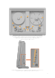
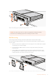
12 1 11 2 3 4 6 5 10 9 8 7 1. Core clamp 2. Roller 3. Particle transfer roller 4. Optional Audio and KeyKode Reader attached via left options interface 5. Tensioner wheel 6. Skid plate 7. Light source 8. Drive wheel 9. Pin registration expansion port 10. Compliance arm 11. Spooler backplate 12. Focus wheel 1 2 3 4 5 6 7 8 1. HDMI 2. PCIe 3. Thunderbolt 3 4. Power supply status 5. Bi-Phase sync / timecode out 6. XLR3 audio input 1 7. XLR3 audio input 2 8.
TIP If you are reading the printed version of this manual that was included with your Cintel scanner, you can also download the latest version in PDF form. The PDF version of the manual includes many different languages and can be downloaded from the Blackmagic Design support center at www.blackmagicdesign.
267mm When desk mounted, you can securely fasten your scanner to your work surface by screwing M6 safety bolts into your scanner’s feet. NOTE Your safety is important to us and we strongly advise reading the warning information on the following page before mounting your Cintel scanner. Wall Mounting Cintel’s elegant industrial design and narrow profile make it ideal for wall mounting. To do this, the first thing you’ll need to do is remove the feet and support strut from the base of your scanner.
The locations of the four M8 mounting screws on your scanner’s back panel are shown below. Be sure to use M8 screws when securing your scanner to a wall mount. The M8 screws should not exceed 25mm in length. 800mm M8 M8 M8 M8 400mm Warning for Safely Installing your Scanner The Cintel Scanner weighs up to 70kg, or 155 pounds, when loaded with film. This is significantly heavier than a large screen television.
Getting Started After unpacking and mounting your scanner, getting started is as simple as plugging in power, connecting your computer via Thunderbolt, launching Blackmagic DaVinci Resolve, and lacing your film. If you want to immediately see your scan on an external monitor, you can load film, manually tension it, and output it to an HDMI monitor. To learn more about this, refer to the ‘lacing film,’ and ‘playback controls’ section of this manual.
Launching DaVinci Resolve Launch DaVinci Resolve and select the Media page. Open DaVinci Resolve’s film scanner panel by clicking on the ‘capture’ button at the top right of the screen and selecting ‘film scanner’. The scanner will capture a large amount of image data, so you’ll need to set the folder you want DaVinci Resolve to record the captured files to. To do this: 1 Launch DaVinci Resolve. 2 Click on ‘preferences’ in the DaVinci Resolve menu bar.
Firmware Updates Cintel Scanner and Audio and KeyKode Reader both have internal firmware that may need an update after you install the Cintel Scanner software on your computer. Cintel Scanner After you install the Cintel Scanner software on your computer and connect the Cintel Scanner, it will determine whether your scanner’s firmware needs an update.
Software Development Kit Blackmagic Design provides a free software development kit for your scanner. The SDK is cross platform so your software can run on Mac, Windows or Linux. The SDK provides example applications that let you control your scanner like in DaVinci Resolve, but from a command line. You can use the Cintel Scanner SDK to develop software to control your scanner, change settings, initiate scans, and process clips.
Drive Wheel Types Cintel Scanner comes equipped with capstans or sprocket wheels depending on the model of scanner. Both types of drive wheels rotate to advance or rewind the film, and then stop to align each frame accurately within the gate of the image sensor. Drive wheels are integral to the scanner and cannot be exchanged for a different type of drive wheel. Capstans grip the film with a moderate amount of friction and are gentle on film with fragile or damaged perforations.
Lacing Film Now that your scanner and DaVinci Resolve are communicating with each other, you can lace up your film. 1 Accessing the Scanner Open your scanner’s sliding doors. On the internal front panel you’ll see a feeding spool on the left, and a taking spool on the right. The feeding spool holds the film to be scanned, and the taking spool collects the scanned film. 2 Setting Film Wind Set the ‘wind type’ so the spools turn in the appropriate direction.
4 Loading Film Load your film reel or core onto the feeder spindle following the same procedure in step 3. Note that the procedure differs slightly depending on whether your film is on a core or a reel, and whether it is 35 or 16mm. For example, when loading a core, you’ll need to insert the provided backing plate, whereas loading a reel only requires the use of spacers. When loading film reels, the backing plate is not required and you can simply use the spacers provided.
6 Tensioning Film To secure your film to the taking spool, insert the end of your film into the small notch provided in the spool, then gently hand wind the spool a few times to hold the film in place. If you don’t want to bend the end of the film inside the notch, you can easily use the friction of the film winding onto itself to secure your film to the spool. You can also use very light adhesive tape.
7 Inspecting your Film Check that the film is laced properly by pressing the ‘play’ button on your scanner or clicking the ‘play’ button in DaVinci Resolve’s film scanner panel. If you see your film image playing in the viewer, or on an HDMI monitor if connected, you’ll know your scanner is working. NOTE Depending on the wind type you’ve used, you may find that the image is flipped horizontally or vertically. You can fix this by selecting the appropriate film type.
TIP The focus assist feature works best when using negative film types, as negative is generally sharper with the most grain detail. To get the most from the focus assist feature, set the viewer to full resolution. Simply click on the options settings at the top right corner of the viewer and select ‘Full Resolution Preview’ from the drop down menu. It’s worth mentioning that full resolution preview will remain set until you choose to disable it.
NOTE The default wind type for your scanner is a B/A wind, meaning the feeding spool unloads from the bottom and the taking spool loads across the top. If the film you are working with has been wound a different way, other combinations of A and B winds are supported; simply select the appropriate wind type via the ‘feed’ and ‘take up’ buttons in DaVinci Resolve’s film scanner panel.
Switching to 16mm The optional Cintel Scanner 16mm gate kit contains all the parts you’ll require and making the changes to your scanner’s setup are minimal. 16mm skid plate Inner spacer Outer spacer The 16mm kit contains a 16mm skid plate, two inner spacers and two outer spacers. Switching to 16mm scanning is easy: 1 Swapping the Skid Plate Swap the 35mm skid plate with the 16mm skid plate by pushing the retention levers down on the front of the 35mm plate and turning them outwards.
2 Inserting the 16mm Inner Spacer Insert the rubber 16mm inner spacer at the base of the feeding and taking spools. The rubber spacer goes on grooved side inwards prior to a backing plate, spool or reel. 3 Additional Spacers (optional) Additional 1mm rubber spacers are included in the 16mm Gate Kit for when mounting a reel. You can use these spacers if you need to adjust the alignment of the film with your scanner’s rollers.
Playback Controls The following playback controls are available in DaVinci Resolve and on your scanner. Your scanner has built in controls for loading, unloading, and previewing scans. Load Pressing ‘load’ will tension the film loaded onto your scanner’s feeding and taking spools as described in the section ‘lacing film.’ Pressing load once your film is properly tensioned will unload the film by returning the compliance arms to their slack position.
Play Plays the film. The default frame rate is 24 frames per second. You can set the playback frame rate and ‘play reverse’ in DaVinci Resolve’s film scanner panel. Step Forward Advances the film one frame. You can also hold down the ‘step forward’ button to play the film forward at slow speed. Fast Forward Rapidly advances the film onto the taking spool. The stopping action performs the same way as rewind for 50, 75 and 100mm spools.
Capturing from Cintel using DaVinci Resolve This section of the manual shows you how to use settings and features in DaVinci Resolve’s film scanner panel to control your scanner. For example calibrating your scanner, adjusting the light source strength and color temperature, setting image stabilization, and more. You can even set how gentle your Cintel scanner handles film which may have become delicate with age. TIP DaVinci Resolve saves all scanner settings in your current project.
Transport Controls: The transport controls under the viewer, while similar in appearance to those used while in playback mode, now work to control the Cintel scanner. Additional controls appear for moving forward or backward a frame at a time. In and Out Controls: In Cintel Scanner mode, the In and Out buttons to the right of the transport controls define a range of the film roll from which to capture.
TIP Calibrate the optics with the skid plate installed and correctly aligned, as this assists with image stabilization and offers the best image quality. Film Type These controls let you select the type of film you’re scanning, align the film with the sensor, and choose what speed you’re scanning at. Film Type controls in the Media page Film Type: Lets you choose what type of film you’re scanning. The choices are positive, negative, interpositive, and internegative.
Scan Speed: With adequate disk performance, you should be able to scan at 30 fps. However, if you’re scanning to a slow hard drive, you can reduce the scanning speed to a frame rate that’s suitable for your workstation without dropping frames. Supply: Sets the wind direction of the left-hand side feed spool. While auto-detection will prevent incorrect operation, you should manually configure the reel winding direction based on how each film roll is wound.
TIP Whenever you change film type, gauge or enable HDR, the auto black/white calibration is reset. The status indicator under the auto black/white button reminds you to recalibrate the LED light source to help ensure the highest quality scans or inform you if any problems occur.
TIP Image stabilization automatically manages vertical gate hop when you select the ‘enable y’ checkbox. It needs no further adjustment and works in conjunction with horizontal stabilization. Adjusting the horizontal position of the stabilization overlay. In this screenshot, the overlay is not aligned with the edge of the perf. Hardware stabilization control correctly positioned over a perforation in the viewer. The transparent stripe in the stabilization overlay touches the edge of the perforation.
TIP To closely check the results of your stabilization settings before capturing, set the viewer to full resolution. Simply click on the options settings at the top right corner of the viewer and select ‘Full Resolution Preview’ from the drop down menu. This setting does not affect the stabilization feature, but enables the best possible preview so you can monitor how well it is performing. It’s worth mentioning that this setting will remain set until you change it back to your previous setting.
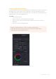
The ‘capture info’ panel lets you specify metadata for your scanned clips Capture Location: Before you begin a film scanning session, scroll down to the ‘capture info’ section of DaVinci Resolve’s film scanner panel to make sure the scanned files are being saved to the directory and volume where you want them. Click the ‘browse’ button and choose a location from the file destination dialog. It’s good to do this first, as this step is easy to forget.
Timestamp Prefix: Select this checkbox to prefix your scans with a timestamp as well as the ‘file name prefix’ you specified. Your clips will be saved to independent subfolders in the destination folder. This checkbox is selected by default. If you want to save all your clips together in one master destination folder without the timecode in the file name, simply deselect the checkbox.
Focus the Scanner Just as you need to focus the lens on a camera, you’ll need to focus the projected film image on your scanner’s sensor. To achieve perfect focus, turn on the Focus Assist checkbox in the Film Scanner capture settings of DaVinci Resolve. This superimposes a focus peaking overlay over the Ultra HD image that’s output from the scanner’s HDMI output, and is also displayed in DaVinci Resolve’s capture window.
Timecode cannot be a negative value, so don’t set the start frame to zero. Another common organizational technique is to change the hour number whenever you change rolls, to coincide with the film roll’s number, which makes it easy to identify a scanned clip with the corresponding source roll and frame range. NOTE Your Cintel Scanner has built in ‘Options Interface’ ports for adding optional hardware in the future.
The film is scanned using the full sensor aperture of 4096x3072 to keep the audio waveform visible for optical audio and to accommodate perforation visibility for stabilization. The image is then cropped and the resolution of the capture files depends on the source film format after overscan for perforations and the audio area are removed. For more information about scanning resolutions for different types of film, see the ‘specifications’ section.
This is important because the light source master wheel and RGB controls cannot be automatically changed between scanned clips in a log and capture workflow. This means that the current light source settings will be used for all clips you scan until you manually change those settings again, even for clips that you’ve logged from different parts of a film roll.
TIP If ‘Enable 2 Pass HDR Scan’ is selected, click ‘Capture HDR’ after the capture has begun to let DaVinci Resolve know you’ve reached the end of your desired clip so it can now proceed to capture the high exposure pass. If you scan the entire reel without clicking ‘Capture HDR’, the scanner automatically proceeds with the high intensity scan from where you started it until the end of the reel. Capture Clip: A more controlled means of scanning specific sections of film.
Extracting Audio If the film you’re scanning also contains an optical sound track, you can extract the audio in a separate step. There is a standard image frame to audio frame offset of 26 frames for 16mm and 21 frames for 35mm that DaVinci automatically aligns when extracting the audio. Select all of the clips that have an optical sound track, then right-click one of the selected clips and choose ‘extract audio’.
Audio Extraction Settings Normally, once you have selected the film type, the automatic features in DaVinci Resolve will extract your optical audio perfectly. However, the condition of the optical track can vary with the condition of the film being loaded and in some instances this can confuse the automation. If this happens, you can bypass the automatic features and make adjustments manually.
Audio extraction settings let you make the following manual adjustments: Show audio scan area This checkbox turns the audio scan area guides on or off. The guides are displayed as a box on the side of the frame covering the optical audio scan area and shows what optical information will be used during extraction. The position of the guides will conform to the film type you have selected. However, you can change the position manually if you need to.
Override audio scan area This setting provides sliders for adjusting the horizontal and vertical positioning, width, and height of the audio scan area guides. These settings include: Left and Width: If your film type is such that audio appears on the right side of the frame, you can simply adjust the ‘left’ slider to move the guide box to the right.
TIP If you haven’t used variable density audio before, you can visually identify it as a tight sequence of shaded lines, similar to a bar code with the lines squeezed closer together. By comparison, ‘variable area’ soundtracks appear as an audio waveform. Color Space and Sizing A pair of 1D LUTs, ‘Cintel Negative to Linear,’ and ‘Cintel Print to Linear,’ have been provided to help you convert scanned media to a color space in which you can do further work.
Once you’ve created an appropriate sizing preset for a given type of media, you can apply that preset to multiple film scans all at once, in either the color page or in the media pool using the ‘change input sizing preset’ command, found in the contextual menu of selected clips. For more information on sizing, see the ‘sizing and image stabilization’ chapter in the DaVinci Resolve manual.
By lacing your film through the upper section of the reader, you can extract optical and magnetic soundtracks from your film. When film is laced through the reader’s lower section, you can capture KeyKode information. KeyKode data is located near the perforation area on some negative film stocks and typically contains data about the position of frames within a reel, information to help identify the film roll, and additional details such as the type of film stock.
3 Remove the upper and lower covers from the Audio and KeyKode Reader by unscrewing the 6 x M3 screws with a 2.5mm Allen key. The screws are ‘captive’ so they remain attached to the reader. Removing the covers gives you access to the captive screws needed to attach the reader to your Cintel scanner. Remove the upper and lower covers from the reader by unscrewing the six M3 cover screws.
6 Fasten the Audio and KeyKode Reader to your scanner using the 3 x captive M3 screws, ensuring it is seated flat to the deckplate before tightening. Plug the reader into the left options interface XLR connector and fasten the reader to your Cintel scanner using the three captive M3 screws.
7 Reattach the Audio and KeyKode Reader covers and tighten the cover screws. Reattach the upper adjustment knob and lightly tighten the retention screw to the flat side of the spindle. Reattach the reader’s covers by tightening the six captive M3 screws and reattach the adjustment knob by tightening the screw against the flat edge of the spindle.
TIP When film is laced through the reader’s audio path, DaVinci Resolve will automatically record audio and add it to your clips. Alternatively, if it is laced through the lower path no audio will be recorded. Setting the Reader for Audio Scanning Once your film is laced, go to DaVinci Resolve’s film scanner panel and set the ‘use film’ and ‘audio type’ settings in the reader accessory pane.
Magnetic Audio: If you want to scan the magnetic striped audio track on 16mm film, set the ‘use film’ setting to ‘magnetic audio’. You can identify magnetic striped audio audio track on 16mm film by looking for a black strip next to the frames. The black strip will be copper colored on the emulsion side of the film. NOTE When scanning magnetic stripe audio, we recommend setting your scan speed to 24 frames per second for proper equalization. Scanning at other speeds may require pitch adjustment in post.
Tracking As the positioning of optical soundtracks can vary slightly from print to print, it is important to ensure that your reader is scanning the correct audio area on the film. The tracking feature on the audio reader lets you make fine adjustments to the position of the optical audio scanning head to ensure you are getting the best possible quality. To use the tracking feature: 1 Plug a set of headphones or an audio analyzer into your reader’s 3.5mm headphone jack.
Previewing Audio via HDMI and the Headphones Jack Film soundtracks are printed several frames ahead of the images they sync to, therefore, your Cintel scanner automatically delays the audio so it is synced to the picture via the HDMI output and also synced in the scanned clip. The headphones jack outputs real time, non-synced audio directly from the soundtrack. This means that when you make tracking adjustments, you can hear the difference immediately without a delay.
Commencing your scan Once you have set your audio type and adjusted the tracking, simply commence your scan as detailed in the section ‘Scanning One or More Sections of Film.’ It’s worth noting that DaVinci Resolve will not begin writing a file until it has synchonized audio and video information being sent from your scanner.
Use Film Use these settings to determine the reader’s KeyKode or audio reading functions. For information on audio reading, refer to the ‘Setting the Reader for Audio Scanning’ section. The settings for the KeyKode reader include: KeyKode Perforations: Select ‘KeyKode Perforations’ to record KeyKode based on the perforation count. KeyKode Frames: Select ‘KeyKode Frames’ with any type of film to record KeyKode accurate to the frame count.
Transcoding to DPX including KeyKode Metadata If you want to, you can also set DaVinci Resolve to transcode your scans to the DPX file format, which will retain all the KeyKode metadata. To transcode your scans to DPX: 1 Go to the menu bar at the top of the screen and click on ‘File’, then select media management. 2 In the media management window, click on the ‘clips’ icon to transcode all clips individually, and select transcode.
To clean the particle transfer rollers, simply remove the O-ring at the end of each PTR spindle and slide off the roller. NOTE If you find your particle transfer rollers losing stickiness even after washing, or have become difficult to mount and remove through age, wear and tear, you can purchase new rollers from the Blackmagic Design website at www.blackmagicdesign.com Cleaning the Capstans Clean the capstans as needed with a small amount of water and a lint free cloth. Allow them to air-dry.
You may occasionally wish to clean the lens over your scanner’s RGB light source. This can be done with a clean cloth and a small amount of isopropyl alcohol. Both air dusters and isopropyl alcohol are available at most electronics stores. Cleaning the Audio and KeyKode Reader Roller The Audio and KeyKode Reader contains a rubber roller for film laced through its upper track. This should be cleaned from time to time with a damp cloth.
Cleaning the Audio and KeyKode Reader’s Magnetic Audio Head You may wish to occasionally clean the Audio and KeyKode Reader’s magnetic head. To clean the magnetic head, remove the top cover of the reader by removing the 4 x M3 screws with a 2.5mm Allen key. Remove the Audio and KeyKode Reader’s upper cover to access the magnetic head With the magnetic head exposed, simply dip a Q-tip in water and shake off any excess, then gently brush the magnetic head surface to remove dust.
Working with Clips in DaVinci Resolve You can use DaVinci Resolve’s ‘clone’ tool, in the ‘media’ page, to create running backups as you scan your clips. This is recommended as any type of media is susceptible to becoming damaged or developing a fault so creating backups ensures your scanned files will be immune to loss.
The project manager shows all projects belonging to the current user For more information about the Project Manager, refer to the DaVinci Resolve manual which is available to download on the Blackmagic Design website support page. Editing with the Cut Page The ‘cut’ page gives you a fast, dynamic editing workflow that lets you quickly assemble, trim and edit clips efficiently. Two active timelines let you work with your entire edit plus a detailed area simultaneously.
For more information on the Cut page, see the ‘Using the Cut Page’ chapter in the DaVinci Resolve manual. Media Tabs At the top left corner of the user interface you will see five tabs. Click on these tabs to open the media toolsets you will use when creating your edit. For example, the first tab is the media pool and you can see it is already selected. The other tabs are for the sync bin, media transitions, titles and effects.
Source Clip The source clip viewer displays a single clip from the media pool and you can set in and out points along the entire length of the viewer timeline. This gives you greater control. Select a source clip to view by double clicking on a clip in the media pool, or dragging it into the viewer. Source Tape Source tape lets you view all the source clips in the media pool. This powerful feature is helpful if you want to quickly search through all your clips to find a specific event.
Adding Clips to the Timeline Now that you are familiar with the media tabs and viewer mode buttons, you can open the media pool and quickly start adding clips to your timeline. The timeline of the cut page, comprising the upper timeline and the zoomed in timeline below The timeline is where you will build your edit and is like a board with tracks you can attach clips to, move them around and trim their edits.
3 Now click the ‘append’ icon underneath the media pool. Your first clip will be placed at the head of the timeline. Repeat steps 1 to 3 to keep adding more clips and they will automatically append, ensuring there are no gaps in the timeline. Appending clips ensures there are no gaps between them on the timeline TIP You can speed up the process further by assigning a keyboard shortcut to the ‘append’ icon.
You can even pick the clip up and drop it on a new video track in the large timeline without having to zoom in or out. This speeds up the edit process because it minimizes time navigating a long timeline. After you have finished editing clips using the ‘cut’ page, you might want to add a title. The next section will show you how. Adding Titles Placing a title on your timeline is easy and you have many options.
TIP It is a good practice to adjust the Blackmagic RAW settings for your clips on the ‘color’ page before you start color grading. Clip Settings for Blackmagic RAW When you first import Blackmagic RAW files, DaVinci Resolve will decode the camera data contained in the files using the ISO, white balance and tint settings used at the time of shooting. If you’re happy with the look of these settings, you can start editing right away.
Saturation Saturation controls default at 1 and range from -1 for the minimum saturation to +4 for maximum saturation. Contrast Defaulting at 1.0, drag the slider to the left for the least amount of contrast at 0 or to the right to increase the contrast up to 2. Midpoint In Blackmagic Design Film, your middle gray value defaults to 0.38, or 38.4%. Drag the slider to the left to lower your midpoint or to the right to raise it to 100.
TIP Gamma controls are disabled for footage shot with the ‘video’ dynamic range, but you have not lost your Blackmagic RAW data. Simply select Blackmagic Design Film or Blackmagic Design Extended Video from the dropdown gamma menu and make your adjustments. Saving your Blackmagic RAW changes 1 Adjust the gamma controls for your Blackmagic RAW clip. 2 Click the ‘update sidecar’ button. A ‘sidecar’ file will now be created in the same folder as your .braw file.
see your work come alive! This is usually the first step and is referred to as primary color correction, or adjusting the primaries. After primary color correction is done, you can then make secondary color correction adjustments which is where you can make extremely precise color adjustments of specific objects in your images.
The ‘lift, ‘gamma’, ‘gain’ and ‘offset’ color wheels give you total control over the color and tonal balance of your clips. To make a uniform adjustment to all colors for each tonal region, drag the dial underneath the color wheels back and forth For more accurate control of each color using a mouse, you can change the color wheels to ‘primaries bars’ which let you adjust each color and luminance channel for the lift, gamma and gain controls separately.
The curves palette is another tool you can use to make primary color corrections, or enhance specific areas of your clip when using a power window Secondary Color Correction If you want to adjust a specific part of your image then you need to use secondary corrections. The adjustments you have been doing up until now using the lift, gamma and gain adjustments affect the whole image at the same time and so they are called primary color corrections.
Sometimes your selection can spill into areas of the shot you don’t want to affect. You can easily mask out the unwanted areas using a power window. Simply create a new window and shape it to select only the area of color you want. If your selected color moves in the shot, you can use the tracking feature to track your power window. Adding a Power Window Power windows are an extremely effective secondary color correction tool that can be used to isolate specific regions of your clips.
Tracking a Window The camera, object or area in your shot may be moving, so to make sure your window stays on your selected object or area, you can use DaVinci Resolve’s powerful tracking feature. The tracker analyzes the pan, tilt, zoom and rotation of the camera or object in your clip so you can match your windows to that movement. If this isn’t done, your correction can move off the selected target and call attention to itself, which you probably don’t want.
OFX plugins are a quick and easy way to create an imaginative and interesting look Mixing Your Audio Mixing Audio in the Edit Page Once you have edited and color corrected your project, you can begin to mix your audio. DaVinci Resolve has a helpful set of features for editing, mixing and mastering audio for your project directly in the ‘edit’ page. For projects requiring more advanced audio tools, the Fairlight page provides you with a full audio post production environment.
Dragging a volume overlay to adjust the clip level For projects requiring more advanced audio tools, the Fairlight page provides you with a full audio post production environment. The Fairlight Page The ‘Fairlight’ page in DaVinci Resolve is where you adjust your project audio.
Tracks: Each track on the Fairlight page is divided into lanes, which show each individual channel of clip audio for editing and mixing. The edit page hides these individual audio channels, displaying only a single clip in the timeline to make it easier to edit multi channel sources without needing to manage a huge number of tracks.
The audio mixer, with channel strips corresponding to the tracks in the timeline Using the Equalizer to Enhance your Audio After adjusting the audio levels of your audio clips in your project, you may find that the audio needs further finessing. In some cases you may find that the dialogue, music and sound effects are competing for the same frequency on the audio spectrum, making your audio too busy and unclear.
Any frequencies outside the cutoff frequency are cut gradually in a downward sloping curve. A shelf filter is less aggressive, and is useful when you want to shape the overall top end or low end of the signal without completely removing those frequencies. The shelf filter boosts or cuts the target frequency and every frequency either above or below it evenly, depending on whether you use a high shelf or low shelf.
To adjust the EQ for a band filter: 1 Select the band filter type from the dropdown menu for the band you want to adjust. 2 Adjust the ‘frequency’ value to select the center frequency of the EQ adjustment. 3 Adjust the ‘gain’ value to boost or attenuate the frequencies governed by that band. 4 Use the ‘Q factor’ value to adjust the width of affected frequencies. Use the reset button to reset all controls in the EQ window to their defaults.
3 Select a preset to use from the top row of icons in the quick export dialog, and click ‘export’. 4 Choose a directory location and enter a file name using the export dialog, then click ‘save’. A progress bar dialog appears to let you know how long the export will take. The quick export dialog The Deliver Page This page lets you select the range of clips you want to export, plus the format, codec and resolution you want.
Now that you have a basic knowledge of how to edit, color, mix audio and add visual effects, we recommend experimenting with DaVinci Resolve. Refer to the DaVinci Resolve manual for more details on how each feature can help you make the most of your project! Reducing Grain using Noise Reduction If you want to reduce the grain in your scanned film, you can use DaVinci Resolve’s powerful noise reduction features.
Temporal NR controls The temporal NR controls analyze images across multiple frames in order to isolate noise from detail. Motion estimation settings let you exclude moving subjects from this operation in order to prevent unwanted motion artifacts. Use the temporal NR settings to clean noise from areas of the frame that aren’t moving. Number of Frames: The number of frames you want DaVinci to average in order to separate detail from the noise. You can choose between 0 and 5 frames.
Luma/Chroma Threshold ganging: Ordinarily, the luma and chroma threshold parameters are ganged together so that adjusting one adjusts both. However, you can ungang these parameters in order to adjust different amounts of noise reduction to each component of the image, depending on where the noise happens to be worst. Motion Threshold: Defines the threshold separating moving pixels in motion, which are above this threshold, versus moving pixels that are static, which are below this threshold.
Setting ‘radius’ to be progressively larger results in higher quality within areas of greater visual detail at high luma and chroma threshold values, at the expense of slower performance. An NR radius of ‘medium’ should provide suitable quality for most images when using medium NR threshold settings. As with many operations, there’s an adjustable tradeoff between quality and speed. Luma Threshold: Lets you determine how much or how little noise reduction to apply to the luma component of the image.
5 If you’re not satisfied with the tradeoff between the maximum possible threshold of noise reduction and the prevention of motion artifacts, you may want to adjust the motion threshold setting, lowering it to omit more of the motion from the noise reduction operation, or raising it to include more motion. If you’re still not satisfied, you can also try better ‘motion est. type’ and ‘motion range’ settings. Keep in mind that the strength of temporal NR is to reduce noise in unmoving parts of the image.
Automatic Dirt Removal In the ‘ResolveFX Revival’ category of DaVinci Resolve Studio, the Automatic Dirt Removal plugin uses optical flow technology to target and repair temporally unstable bits of dust, dirt, hair, tape hits, and other unwanted artifacts that last for one or two-frames and then disappear. All repairs are made while maintaining structurally consistent detail in the underlying frame, resulting in a high quality restoration of the image.
Deflicker In the ‘ResolveFX Revival’ category of DaVinci Resolve Studio, the Deflicker plug-in handles such diverse issues as flickering exposure in timelapse clips, flickering fluorescent lighting, flickering in archival film sources, and in certain subtle cases even the “rolling bars” found on video screens shot with cameras having mismatched shutter speeds.
Motion Range: Three settings, Small, Medium, and Large, let you choose the speed of the motion in the frame that should be detected. Gang Luma Chroma: Lets you choose whether to gang the Luma and Chroma Threshold sliders or not. Luma Threshold: Determines the threshold above which changes in luma will not be considered flicker. The range is 0–100, 0 deflickers nothing, 100 applies deflickering to everything. The default is 100.
Dust Buster In the ‘ResolveFX Revival’ category of DaVinci Resolve Studio, this plugin is also designed to eliminate dust, dirt, and other imperfections and artifacts from clips. However, it does so only with user guidance for clips where the ‘automatic dirt removal’ plugin yields unsatisfactory results. This guidance consists of moving through the clip frame by frame and drawing boxes around imperfections you want to eliminate.
Specifications 1055mm 360mm 880mm 2010mm Weight: 60 kg (132 lb) unloaded. Dimensions wall mounted: (H) 785mm, (D) 265mm Scanner Features Film Stocks Effective Resolutions1 Dirt and Scratch Reduction - Print, Negative, Interpositive, Internegative. 3840 x 2880 - Super 35 - Diffuse light source - Cleaning Rollers - Mono and Colour.
Connections HDMI Video Output Bi-phase/Timecode Output3 AES/EBU Audio Input 1 x HDMI 1.4 10-bit 4:2:2 for preview purposes only. - Bi-phase 4.5 Volt DC Coupled 1 Channel with sample rate converter on XLR connector. - Timecode 1.5 Volt DC Coupled Options Interface XLR6 - Timecode support for 24, 25 and 30 fps Computer Interface2 Analog Audio Inputs -T hunderbolt™ 3 for capture of image and audio, software updates and supports USB-C charging with 15W at 5V.
Accessories - Cintel Audio and KeyKode Reader - Cintel Scanner 35mm Gate HDR -C intel Scanner 16mm Gate HDR - Cintel Cleaning Roller Kit - Blackmagic PCI Express Cable Kit Audio and KeyKode Reader Equalisation Optical Audio 35mm Full Modulation Level Optical audio SMPTE, Magnetic audio IEC Bandwidth 40Hz-16kHz +-2dB -18dBFS Supported KeyKode Scan Speeds SnR Signal to Noise Ratio4 Transparent film base -65dB All scanner speeds Supported Audio Scan Speeds 6fps-125% chosen film rate -18dBu
Regulatory Notices Disposal of waste of electrical and electronic equipment within the European union. The symbol on the product indicates that this equipment must not be disposed of with other waste materials. In order to dispose of your waste equipment, it must be handed over to a designated collection point for recycling.
No operator serviceable parts inside product. Refer servicing to your local Blackmagic Design service center. Use only at altitudes not more than 2000m above sea level. State of California statement This product can expose you to chemicals such as trace amounts of polybrominated biphenyls within plastic parts, which is known to the state of California to cause cancer and birth defects or other reproductive harm. For more information go to www.P65Warnings.ca.gov.
Help The fastest way to obtain help is to go to the Blackmagic Design online support pages and check the latest support material available for your Cintel scanner. Blackmagic Design Online Support Pages The latest manual, software and support notes can be found at the Blackmagic Design support center at www.blackmagicdesign.com/support. Blackmagic Design Forum The Blackmagic Design forum on our website is a helpful resource you can visit for more information and creative ideas.
USB Recovery In the unlikely event the update was interrupted, or you encountered an issue during the update process and your Cintel has become unresponsive, you can plug your computer into a dedicated USB port for USB recovery. You can confirm that USB recovery is available by powering your Cintel and checking that the status LED near the Thunderbolt port is illuminated green. If the LED is illuminated red, you will need to contact Blackmagic Design support.
3 Download the latest version of the Cintel Scanner software from the Blackmagic Design website, install it on your computer and run it. The Cintel Setup utility will detect your computer is plugged into your Cintel Scanner’s USB recovery port. Click ‘update now’. Cintel Scanner software will detect your computer is plugged into Cintel’s USB recovery port 4 After the update recovery is complete, your Cintel Scanner should now be running the latest software and operating normally.
Warranty 12 Month Limited Warranty Blackmagic Design warrants that this product will be free from defects in materials and workmanship for a period of 12 months from the date of purchase. If a product proves to be defective during this warranty period, Blackmagic Design, at its option, either will repair the defective product without charge for parts and labor, or will provide a replacement in exchange for the defective product.