Cerebus™ Stim Switch 128 Channel USERS MANUAL STIMULATION AND RECORDING SWITCHING (REVISION 1.00) Blackrock Microsystems, Inc. 391 Chipeta Way, Suite G Salt Lake City, UT 84108 Tel: (866) 806-3692 www.blackrockmicro.
CerebusTM Stim Switch 128-Channel Users Manual © Copyright 2010 Blackrock Micosystems, Inc. All rights reserved. Copying or other reproduction of this document is prohibited without prior written consent of Blackrock Microsystems, Inc. CerebusTM is a trademark of Blackrock Microsystems, Inc. Rev. 1.
CerebusTM Stim Switch Users Manual Table of Contents 1 System Overview ............................................................................................................................1 1.1 Packing List .............................................................................................................................................................. 1 2 Hardware.............................................................................................................................
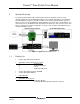
CerebusTM Stim Switch Users Manual 1 System Overview The Cerebus Stim Switch provides unprecedented electrode-switching control for neural stimulation applications by enabling high-quality neural recordings immediately after stimulation. The Stim Switch is designed as an add-on module for the Cerebus data acquisition system. It allows researchers to programmatically switch individual electrodes between a stimulation source and a Cerebus front-end amplifier.
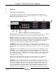
CerebusTM Stim Switch Users Manual 2 Hardware 2.1 Stim Switch Control Module The Stim Switch Control Module interfaces the Headstage Module with the digital control computer and analog stimulation source. Stim Switch configuration is accomplished using the StimComm program described in Section 3. Figure 2-2: Stim Switch Control Module Front Panel Power Switch (1): Use the power switch to turn on the Stim Switch Control Module.
CerebusTM Stim Switch Users Manual Table 2-1: Behavior of the Enable In Port Voltage Behavior 3.3 V Normal Operation. All channels behave as set by the StimComm software. 0V All channels set to recording mode when the StimComm software is set to either recording or stimulation mode. When in blanking mode, the Enable In switch has no effect.
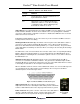
CerebusTM Stim Switch Users Manual plugging in the Stim Switch for the first time. There are also two fuses in the power supply that may need to be replaced if the Power Supply is connected to the wrong voltage. 2.2 Stim Switch Headstage Module The Headstage Module provides connection between the Cerebus Front End Amplifier, the electrodes, and the Stim Switch. LEDs on the module indicate power (1), blanking enabled (2), and stimulation enabled (3).
CerebusTM Stim Switch Users Manual 2.3 Computer Setup The Stim Switch connects to a USB port on the computer through a standard USB A-B cable. The StimSwitch uses an internal USB to serial converter and will appear as a COM port on your computer. Be sure that the COM assigned by your computer to the Stim Switch matches the COM port settings in the StimComm Software (See Figure 2-7 Stim Switch Computer Interface Menu Options in section 3 for instructions on changing COM port settings). 2.
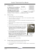
CerebusTM Stim Switch Users Manual 3. Using the StimComm software, select the desired channels for stimulation by checking the boxes next to the electrode numbers and pressing the ‘Set Electrodes’ button. Electrode numbers can be selected independently for each bank of stimulation channels by selecting the tabs at the top of the window. 4. Connect a control device to the Enable In inputs using a BNC cable. The control devices can be any device that toggles between 0 V and 3.3 V (2.
CerebusTM Stim Switch Users Manual 3 StimComm Software The StimComm software runs under Windows XP Professional, Windows Vista, or Windows 7. The StimComm software can be installed from the supplied CD by running the setup.exe program. Once the program has been installed, the StimComm software can be started by double clicking the StimComm desktop shortcut that was created by the installation program, or by launching the StimComm.
CerebusTM Stim Switch Users Manual Control On: This mode allows for continuous stimulation of the selected bank. The Control On feature can be used as a method for manually controlling switching between stimulating and recording. Turn stimulation on by pressing the ‘Set Stim’ button. Click the ‘Set Record’ button to switch to recording mode. Enable A-D: This feature assigns single or multiple Enable In connectors to the stimulation inputs on the selected bank.
CerebusTM Stim Switch Users Manual button must be pressed after each timing cycle in order to begin timing again. This button can also be used to manually stop the timing cycle. Active Timer Panel (5): This panel displays the banks that are actively undergoing periodic switching after the ‘Start Timer’ button is pressed. Menu Options (6): Saving and Restoring Settings: The StimComm program allows you to save current settings to a file and restore those settings later.
CerebusTM Stim Switch Users Manual 4 System Specifications CEREBUS STIM SWITCH Stimulation Inputs 4 DB-37 front panel connectors 1.3 kΩ impedance between input and output when stimulation mode is enabled. > 10 MΩ input impedance when stimulation mode is disabled Recording Outputs 36 Channel Samtec Connector with 32 output channels plus reference and ground pins. 1.1 kΩ impedance between input and output when read mode is enabled. > 10 MΩ output impedance when read mode is disabled.
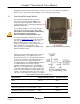
CerebusTM Stim Switch Users Manual 5 Troubleshooting I live in a country with 220 V power, but the back of the Stim Comm Control Module says 110 V. You can change the power supply voltage rating by flipping open the panel above the plug on the back of the module and rotating the wheel so that it says 220 V. The Blanking Box is not visible when I open StimComm. 1. Click on the Startup Menu. 2. In the Search Box, type regedit.
CerebusTM Stim Switch Users Manual Switch Control Module should be green. If it is red try disconnecting the Stim Switch cable and ensuring that both ends are plugged into the Headstage Module and the Control Module correctly. They are keyed and should only be inserted one way. Rev. 1.00 LB-0265 3. Watch the light above the USB port on the Stim Switch when you send a command. It should flash green briefly when the command is sent.
CerebusTM Stim Switch Users Manual 6 Warranty Blackrock Microsystems, Inc. warrants that its products are free from defects in materials and manufacturing for a period of one year from the date of shipment. Blackrock will, at its option, repair or replace any product that does not comply with this warranty. This warranty is voided by: 1. Any modification or attempted modification to the product done by anyone other than an authorized Blackrock employee 2.