Cerebus® Neural Signal Processing System User’s Manual (Revision 13.00) 391 Chipeta Way, Suite G Salt Lake City, UT 84108 866-806-3692 www.blackrockmicro.com support@blackrockmicro.
Cerebus® User’s Manual Table of Contents TABLE OF CONTENTS.............................................................................................................................................. 1 TABLE OF FIGURES ................................................................................................................................................. 4 SYMBOLS OF CONTRAINDICATIONS, WARNINGS, CAUTIONS................................................................................. 6 WARNINGS ..
Cerebus® User’s Manual Analog Output.....................................................................................................................................................29 Digital In ..............................................................................................................................................................30 Digital Out ............................................................................................................................................
Cerebus® User’s Manual TOC Interface ......................................................................................................................................................63 REMOTELY CONTROL DATA RECORDING ...........................................................................................................................64 VISUALIZE AN INPUT CHANNEL ON THE DIGITAL OSCILLOSCOPE .............................................................................................
Cerebus® User’s Manual Table of Figures FIGURE 1 - SYSTEM OVERVIEW............................................................................................................................................11 FIGURE 2 – NEURAL SIGNAL AMPLIFIER ................................................................................................................................12 FIGURE 3 - AMPLIFIER POWER SUPPLY.......................................................................................................
Cerebus® User’s Manual FIGURE 45 - ACTIVITY MONITOR .........................................................................................................................................51 FIGURE 46 - SIGNAL TO NOISE RATIO ...................................................................................................................................52 FIGURE 47 - NEURAL MODULATION ..........................................................................................................................
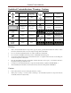
Cerebus® User’s Manual Symbols of Contraindications, Warnings, Cautions N M Y g IEC60101-0102 Danger of Electrostatic Discharge (ESD) IEC60417-5019 Protective earth (ground) IEC60417-5036 Dangerous voltage IEC60417-5021 Equipotentiality Connector IEC606417-5335 Type of CF Applied Part IEC60417-5007 ON (power) IEC60417-5008 OFF (power) IEC60417-5010 ON/OFF (push/push) CSA 60950-1-03 UL 60950-1 Class 1 Laser Product EN-980 Serial Number EN-980 Manufactured date EN-980 Manufacturer E
Cerebus® User’s Manual Specifications Model Name Cerebus® Neural Signal Processor Power Requirements 110 (at 60 Hz) or 240 (at 50 Hz) VAC, 8.0 Amps maximum load Serviceable Fuses 5 x 20mm, 250V, 1.
Cerebus® User’s Manual Table 204 – Guidance and manufacturer’s declaration – electromagnetic immunity – for all EQUIPMENT and SYSTEMS that are not LIFE-SUPPORTING (refer to 60601-1-2). Guidance and manufacturer’s declaration electromagnetic immunity — The Cerebus® System is intended for use in the electromagnetic environment specified below. The customer or the user of the Cerebus® system should assure that it is used in such an environment.
Cerebus® User’s Manual Table 206 – Recommended separation distances between portable and mobile RF communications equipment and the EQUIPMENT or SYSTEM - for EQUIPMENT or SYSTEMS that are not LIFE-SUPPORTING (refer to 60601-1-2). Recommended separation distances between portable and mobile RF communications equipment and the Cerebus® system The Cerebus® system is intended for use in an electromagnetic environment in which radiated RF disturbances are controlled.
Cerebus® User’s Manual Introduction The Blackrock Cerebus® Neural Processing System supports recording, processing and displaying bio-potential signals from various types of electrodes. Bio-potential signals may include Electrocorticography (ECoG), electroencephalography (EEG), electromyography (EMG), electrocardiography (ECG), electrooculography (EOC) action potentials (AP), and evoked potentials (EP).
Cerebus® User’s Manual System Schematic Experiment Operation Area Neural Electrodes with less than 1Megohm Impedance HighImpedance Neural Electrodes Optional 1X Follower Headstages Neural Signal Simulator for System Testing OR Front End Amplifier Fiber Optic Isolation Experiment Subject Area Analog and Digital Experiment Signals System Operator Neural Signal Processor Cerebus Interface Software running on User's PC Front End Power Supply Optional Ethernet Switch Neural Data Files Cerebus Soft
Cerebus® User’s Manual Hardware Neural Signal Amplifier The Amplifier receives analog signals directly from the electrodes or via headstages (e.g. unity-gain voltage followers) depending on the impedance of the electrodes. The analog signals are amplified, filtered (1st-order highpass at 0.
Cerebus® User’s Manual Neural Signal Processor (NSP) Figure 4 - NSP Front Figure 5 - NSP Back The NSP is the real-time processor of the system. It performs all the digital processing of the signals, such as digital filtering, spike extraction, spike sorting. It also processes the data and transmits it to the Host PC through Ethernet UDP protocol. The NSP has multiple analog and digital input and outputs that can be programmed through the software or one of the supplied Software Development Kids (SDKs).
Cerebus® User’s Manual Figure 6 - Digital In Pin Diagram 5) Serial I/O: The port is an RS232 DB9 digital input/output port. The pin diagram is shown below. Currently, the software only supports this port as an input. Pin 2 is “Receive Data”, pin 3 is “Transmit Data”, and pin 5 is “Ground”. The configuration of the port is: Baud rate: 115200, Data bits: 8, Parity: none, Stop bits: 1, Flow control: disabled. Figure 7 - Serial I/O Pin Diagram 6) Analog Outputs: Four ±5.
Cerebus® User’s Manual Connectors, Cables, etc. Headstage Requirements The high input impedance and low bias current of the Amplifier inputs make it possible to connect microelectrodes with 20 kΩ (at 1kHz) or lower impedance values directly to the Amplifier inputs without the need for a headstage. This configuration has the advantage of avoiding noise added to the signals by the headstage, but it makes the application more susceptible to environmental electromagnetic noise.
Cerebus® User’s Manual Neural Signal Amplifier Input The Amplifier has four 34-pin banks. Each bank consists of 32 channels, a bank reference pin, and a ground pin. The electrodes within each bank are differentially amplified with respect to the reference input of the same bank. If channels on all banks are to be electrically measured with respect to a common reference, this reference needs to be connected to the reference input on every bank.
Cerebus® User’s Manual Cables Included with the system is a power cable for the NSP (not shown), a power cable for the APS (not shown), a fiberoptic link that connects the Amplifier to the NSP, a crossover Ethernet cable that connects the NSP to the host PC, and a cable that connects the APS to the Amplifier. Note that the fiber-optic cable is very delicate. Please do not bend it (bend radius of 5.
Cerebus® User’s Manual Neural Signal Simulator (NSS) The NSS supplies simulated field potentials and action potentials (spikes). It can be used to test the system in lieu of a connected subject. The NSS is powered by four AA batteries that can be accessed by removing the back screws and the back plate. The black pin, as shown in the figure below, is NSS Ground. Figure 13 - Neural Signal Simulator 1 Gbps Ethernet Card The supplied Ethernet Card is to be installed in a 64-bit PCI slot of the Host PC.
Cerebus® User’s Manual Setup Hardware Setup Ethernet Card Setup Note: If you purchased the Cerebus® Host PC, the Ethernet card is pre-installed and configured in your PC. The supplied 1-Gbps PCI Ethernet card needs to be installed in a 64-bit PCI slot of the host PC and a crossover Ethernet cable (included) is needed to directly connect the host PC to the NSP.
Cerebus® User’s Manual Figure 15 - Network Connections Window Figure 16 - Local Area Connections Properties Figure 17 - IPv4 Properties Note: Up to 16 PCs can be connected to the same NSP using a business class 1-Gbps network switch with QoS feature. For other PCs connected using a network switch, IP addresses should increment, such as 192.168.137.2, 192.168.137.3, etc. Note: For your reference, the NSP’s IP address is 192.168.137.128. Revision 13.
Cerebus® User’s Manual Data Acquisition Software Cerebus® Central Suite Installation To install the software suite, make sure any previous version of the software is uninstalled. Run the CerebusCentral-Suite msi program from the supplied Installation CD and follow the instructions. The Cerebus® Central Suite consists of several applications that perform various functions. To run these apps first run the Central shortcut via the Start Menu.
Cerebus® User’s Manual Digital Filters The sampled signals are analog filtered by the Amplifier at cut-off frequencies of 0.3 Hz and 7.5 kHz. Additionally, the NSP has standard digital filters that can be applied to signals from the Amplifier and the auxiliary analog inputs. These filters are described below: o None: No digital filter is applied. o HP 750Hz (Spike Narrow): High-pass filter at 750 Hz. o HP 250Hz (Spike Medium): High-pass filter at 250 Hz.
Cerebus® User’s Manual Central Central is the main app launcher. To run Central, double click on the desktop shortcut. Alternatively, you can click on Start, navigate to the Blackrock Microsystems folder, and click on the Central shortcut. This app has shortcuts to all the other apps in the suite. Clicking each button will open the corresponding app. Clicking Reset will set the timestamps on the NSP back to zero. Using reset mid-experiment will reset all digital event timestamps and is not recommended.
Cerebus® User’s Manual o Hardware Standby and Close: Closes Central and all associated applications. If data is being recorded a warning will pop up with an option to stop recording prior to NSP going into “Standby” mode. The NSP must be in “Standby” mode for firmware updates. o Hardware Shutdown and Close: Closes Central, all its associated applications and stops the NSP. Manually turn off the NSP power switch to shut down the system.
Cerebus® User’s Manual Options: Set to various general options for the Central app. Figure 20 - Central Options o Allows multiple instances of: This section lets you open more than one of the window types that are checked. o Do Not Log Sort Changes: Will not automatically log sort changes. o Log Sorting Changes on ‘Record’: Will automatically log the spike-sorting model, the signal to noise ratio summary, and the crosstalk summary only if gets rebuilt during a recording session.
Cerebus® User’s Manual Hardware Configuration To access this app click on Hardware Configuration on the Central app. This app is for setting up channels and various other parameters. It also allows the user to define the sampling frequency, filtering parameters, and many other features for each individual channel. Further, the user can set other global and spike-sorting variables too. Figure 21 - Hardware Configuration By default, only one instance of Hardware Configuration can be opened.
Cerebus® User’s Manual Front-end Amplifier Inputs This window will allow the user to set different properties of a specific channel or a group of selected Amplifier channels. Figure 22 - Analog Input Properties o Label: A user-defined name for the specific channel. When configuring a group of channels you can label them on a global basis by clicking the Edit button. o Digital and Analog Range: Fixed values for informational purposes. o External Gain: Set the gain to match the headstage gain value.
Cerebus® User’s Manual Analog Input This window will allow the user to set different properties of a specific or a group of selected analog input channels. All the options are the same as those of the Amplifier inputs except that the coupling can also be determined for each analog input channel. Figure 23 - Analog Input Properties o AC Coupling: The coupling for each analog input channel is user selectable between AC and DC coupled.
Cerebus® User’s Manual Analog Output This window will allow the user to set the properties of the analog outputs transmitted to other equipment connected to the NSP. Figure 24 - Analog Output Properties o Label: A user-defined name for the specific channel. o Input and Output Range: Fixed values for informational purposes.
Cerebus® User’s Manual Digital In This window will allow the user to set the properties of the digital inputs received from other equipment connected to the NSP. Figure 25 - Digital Input Properties o Label: A user-defined name for the specific channel. o Function: The functions may include: o 16-bit on word strobe: reads 16-bits on strobe. 16-bit on bit changes: reads 16-bits when any bits change, falling or rising. 16-bit on rising edge: read 16-bits when any bits get set high.
Cerebus® User’s Manual Digital Out This window will allow the user to set the properties of the digital outputs transmitted to other equipment connected to the NSP. Figure 26 - Digital Output Properties o Label: A user-defined name for the specific channel. o Properties: The user has the option to Monitor Electrodes, which will send a TTL pulse from that specific Digital Output every time a spike is detected on a specific channel or unit of a channel.
Cerebus® User’s Manual Serial I/O This window displays the serial communication parameters, and allows the user to enable serial communication with the NSP. These values cannot be changed. Figure 27 - Serial I/O Properties Audio This window allows the user to set the properties of the audio outputs transmitted to other equipment connected to the NSP. Figure 28 - Audio Properties o Label: A user-defined name for the specific channel.
Cerebus® User’s Manual Global Settings Figure 29 - Global Settings o Spike Properties: Define variables related to the size of a spike-triggered spike. o Spike Width: Allows a user definable number of samples to be collected in the spike-triggered processing window. The default value is 48 samples. This would collect spike-triggered waveforms for 1.6-ms. The spike width can be set as small as 30 samples (1.0 ms) and as large as 128 samples (4.3 ms).
Cerebus® User’s Manual Filters This window provides specifications of the various filters set in the Cerebus® system. The filters can be set for each channel individually. For graphical details and specifications, click the digital filter dropdown box and select a filter. Figure 30 - Filter Properties Revision 13.
Cerebus® User’s Manual Auto Thresholding This window allows the user to specify the auto thresholding properties for spike detection. Figure 31 - Auto Thresholding Properties o Threshold Multiplier: The signal is filtered between 1-5 kHz (2nd-order Butterworth) for spike detection and the noise in that band is estimated. The signal value has to cross the average noise times the Threshold Multiplier. This value should typically be between 2.0 and 3.0.
Cerebus® User’s Manual Spike Sorting This window allows the user to specify the rules and settings used with the automatic spike sorting. The default settings are recommended, but can be changed to user preference. Figure 32 – Histogram Peak Count Spike-sorting Properties Figure 33 – Manual PCA Spike-sorting Properties o Method: Choose between the automatic Histogram Peak Count and Manual PCA methods.
Cerebus® User’s Manual o Close Peak Percentage: For a second peak to be found, the second peak height needs to be greater than the height of the valley + the height of the 3 points around the peak * the close peak percentage (second peak height > valley height + (3-point mean around valley * close peak percentage)). o Freeze Time (minutes): Time Specified in minutes that the spike-sorting process of determining the number of units per channels runs.
Cerebus® User’s Manual Adaptive Filtering Recorded signals may contain some noise from any known sources of external noise, such as magnetic eye-tracking systems. Such external noise sources may be plugged into the Cerebus® System and tested for extraneous noise levels. The Adaptive Filtering utility provides a means to determine how much of the recorded signal is comprised of noise so that parameters can be set to eliminate the noise from the signal.
Cerebus® User’s Manual N-Trode Groups An N-Trode is a set of electrode channels that are defined by the user. N-Trodes are often used in electrophysiology to record extracellular field potentials and spikes. The bundle of electrodes can record signals from an overlapping population of neurons and therefore it can be used as a powerful tool to enhance spike sorting. In Central, the user can have multiple N-Trode sets. Each N-Trode set can contain up to 4 electrodes.
Cerebus® User’s Manual Spike Panel This app displays the detected spikes on all of the front-end channels. Double click on any channel to display its events in the Single Neural Channel window (explained later). Use the or keys to select several channels to highlight. Channel selection and other display properties can be turned on or off through the right-click context menu.
Cerebus® User’s Manual o Broadcast Channel Selections: Select this button broadcast the selected channels to other computers that may also be connected to the Cerebus® system through an Ethernet connection. o Level of Criticality (LOC): The LOC button displays the load on the PC. Revision 13.
Cerebus® User’s Manual Raster Plot The Raster Plot screen displays spikes as a pixelized image, each pixel representing a signal impulse sampled for the length of time set by the user in the drop-down box. In this example, 50 pix/sec indicates that each second of data is represented by 50 pixels on the screen. Continuous analog data can also be shown. Figure 37 – Raster Plot o Play: When selected, Raster Plot displays wrap. o Scroll: When selected, Raster Plot displays scrolls.
Cerebus® User’s Manual Single Neural Channel This app displays the activity of a single channel. It is also where units can be defined for the manual spike-sorting algorithms. Figure 38 - Single Neural Channel o Channel ID: From the drop down box, change the channel displayed. o Auto: Toggles thresholding between adaptive threshold and a user defined fixed value. o Properties: Display and change the settings of the current channel. o Spike Display: The signal is displayed as time stamped events.
Cerebus® User’s Manual and draw an ellipse in the Pattern view around the cluster that you would like to define as a spike. You may also change the size of the ellipse to make the diameter larger or smaller. Once the ellipse is placed in the cluster that you are defining, the word “Overridden” will appear next to the sorted unit. You can also change the threshold radius by changing the diameter of the grey ellipse in the center of the Pattern Display.
Cerebus® User’s Manual File Storage TOC Interface Use the File Storage Interface screen to record data. The user can enter patient information and select a path for the files that are created when the session is initiated. The Cerebus® Software assigns a numeric name to the files. The numeric file name indicated the data and time of recording. For example, 20110124-152145 indicated that the data file was recorded on January 24, 2011 at 3:21:45 PM.
Cerebus® User’s Manual 2.x Interface Use this window to record data. Some of the controls are similar to the TOC Interface. There are some additional controls that are described below. Figure 40 - File Storage - 2.x Interface o File Options allows the user to enable or disable recording of a certain frequency data. o File Name and Path: Click on Browse to choose a folder to record in and name the data file.
Cerebus® User’s Manual File Storage Options Click on View and then Options to set file storage options. Figure 41 - File Storage Options o Enable Sync Pulse: Will send a sync on Digital Output 1. The sync signal is a unique waveform pattern sent every 14 seconds and repeats itself every hour. Each 14 seconds the pattern changes. This can be used to synchronize recordings with external equipment. o Invert Sync Pulse: It will invert the sync pulse. The pulse will start high and will go low.
Cerebus® User’s Manual Digital Oscilloscope The oscilloscope app is capable of displaying up to two traces of analog input channels on the screen at a very high resolution of 0.1 ms/div. Figure 42 - Digital Oscilloscope View o Channel Enable: The user can enable up to two channels per instance of the oscilloscope. o Channel Selection: Select any channel from the drop down menu. o Color Selection: Allows the user to select a color for either of the traces.
Cerebus® User’s Manual Normal: The trace will freeze as soon as the trace crosses threshold until the trace crosses the trigger level again in which case the screen will update with the new trace. o o Single: A single trace is captured as soon as it crosses the trigger level. To capture another threshold-crossed trace click on Single again. You can set the trigger lever by either entering a voltage value in the field or by sliding the trigger up and down manually using a mouse.
Cerebus® User’s Manual Digital Filter Design This tool is used to design custom digital filters. The allowable filter types of “High Pass”, “Low Pass”, “Band Pass”’, and “Band Reject”. This application depends on MATLAB Compiler Runtime installation. This file is included in your Installation CD. Please contact support@blackrockmicro.com if you need a copy of this file. Figure 44 - Digital Filter Editor The user can select one of the filter types and then select the desired frequency range.
Cerebus® User’s Manual Analysis Software Activity Map This app gives the user an overview of the firing rates of each electrode spatially organized over time. A map file can be loaded to change the electrode arrangement. The spiking activity of each channel is binned and smoothed. Binning is counting the number of spikes that occur over a fixed time window (20ms).
Cerebus® User’s Manual Signal-to-Noise Ratio Signal-to-Noise Ratio (SNR) displays the running amplitudes (µV) of the signal, noise, and signal-to-noise ratio for units on a particular channel. It also displays the signal-to-noise ratio as a function of time, which allows signal quality to be monitored across time. This information can be saved as a tab-delimited text file and opened in Excel or a compatible program for further analysis. In the example below the SNR for elec11 unit 3 is 9.
Cerebus® User’s Manual Impedance Tester Note: A patient cable is required for impedance measurements. Contact Blackrock Microsystems Sales at sales@blackrockmicro.com for more information Impedance Tester runs an analysis on each channel to ensure proper impedance of every electrode. When selected, a dialog box is displayed instructing the user to flip the impedance switch located on the patient cable to the impedance position, marked with a + sign.
Cerebus® User’s Manual Crosstalk If you suspect that you may be looking at the same neural activity on more than one channel, the Crosstalk Diagnostic module will compare each channel for cross correlation. The Crosstalk Diagnostic Module will display each channel as green, yellow, or red. Figure 49 - Crosstalk o Green indicates that no cross correlation to any other channel was found.
Cerebus® User’s Manual N-Trode The N-Trode utility is used when electrode types with multiple recording points are located on the same shank or in the same discrete area of an electrode array. Figure 50 - N-Trode Utility o Before being able to use this utility N-Trode groups need to be defined in Hardware Configuration as described in NTrode Groups on page 39. The N-Trode groups can also be defined from within the N-Trode application window.
Cerebus® User’s Manual Other Utilities Central Play CentralPlay is a tool for replaying pre-recorded digital data (NEV file type) back for review and re-sorting using hoops. A recorded video may also be played back in sync with the recorded data. To run, click on Start and navigate to the installation folder of Cerebus® Central Suite and click on the CentralPlay shortcut. A clock with a sliding bar allows the user to pause, rewind and replay the data file.
Cerebus® User’s Manual nPlayServer (not included) The N-Play experimental playback utility allows the user to load a raw data (NS5 file) previously recorded, and play the data back to duplicate a live recording session. When playing back the raw data file, the user can filter the data, spike sort, and record additional data files from the raw data. The Cerebus® hardware does not need to be connected to the PC to use this utility. Note: nPlayServer is not a part of the Central installation.
Cerebus® User’s Manual How To? Create a Digital Filter Custom digital filters can be defined and used. To create a digital filter do the following: 1) 2) 3) 4) 5) 6) 7) Open Central. Click on Digital Filter Editor. Allow for the Digital Filter Editor to open. This tool requires MATLAB Core Run-time which is available on the Cerebus® Installation CD or can be downloaded from our website. Choose a filter type and the corner frequencies desired.
Cerebus® User’s Manual Set a Threshold Value for Spike Detection Spikes are extracted when the signal crosses a previously set threshold value. There are several ways to set threshold values for spike extraction. Automatic threshold 1) 2) 3) In Hardware Configuration, click on Analog Input and choose the channels of interest. Right click and choose Properties or click on the Properties icon on top of the window. Select Auto Threshold.
Cerebus® User’s Manual Sort Units The Central software offers three automatic and manual methods for real-time spike sorting. Histogram Peak Count (Automatic) 1) 2) 3) 4) 5) 6) 7) 8) Open Hardware Configuration window. Select the channels that need to be spike sorted. Right click and choose Properties or click on the properties icon. Choose “Histogram Peak Count” from the spike-sorting drop down menu. Click OK. Click on Central. Click on Tools. Click on Rebuild Spike Sorting Module.
Cerebus® User’s Manual Hoops (Manual) 1) 2) 1) 2) 3) 4) 5) Open Hardware Configuration window. Select the channels that need to be spike sorted. Right click and choose Properties or click on the properties icon. Choose “Hoops” from the spike-sorting drop down menu. Open Single Neural Channel. From the drop down menu choose the desired channel. Make sure the unit icon is pressed down so you can see the units window.
Cerebus® User’s Manual Manual PCA 1) 2) 3) 4) 5) 6) 7) 8) Open Hardware Configuration window. Select the channels that need to be spike sorted. Right click and choose Properties or click on the properties icon. Choose “Manual PCA” from the spike sorting drop down menu. Open Single Neural Channel. From the drop down menu choose the desired channel. Make sure the unit icon is pressed down so you can see the units window. Click on the Feature tab. Figure 54 - PCA Space 9) Click on Build PCA.
Cerebus® User’s Manual Record a Data File There are two file recording interfaces to choose from. These interfaces can be selected from the options under Central. To open this window click on Tools and then Options. Under “File Storage App Interface” there are two options to choose from. The “2.x Interface” allows a simple interface for recording files. The TOC Interface is generally used with the clinical research customers as it involves fields such as patient ID, etc. 2.
Cerebus® User’s Manual Remotely Control Data Recording The recording can be controlled remotely via an external device, such as a behavioral control system. The remote signal can be sent to the NSP through the digital input or the serial input. The recording can be remotely started, stopped, paused, or a new session can be started. To setup remote recording using individual digital bits do the following: 1) 2) 3) 4) 5) 6) Open Central. Open the File Storage app. Click on Remote Recording.
Cerebus® User’s Manual Re-arrange the Electrodes on Spike Panel (i.e. Create a Map File) It is possible to re-arrange the electrode positions on Spike Panel and Activity Map. To do this, a plain text file needs to be created that contains information on where each channel is to be displayed on the screen in relation to all the other channels. The sample below is an example of such a map file and it’s resulting orientation.
Cerebus® User’s Manual (channel 6) is named elec03 and it should be placed on the 3rd column (2) from left and the 1st row from bottom (0). Note that location positions start from 0. Note: Any line that starts with “//” will be used as comment and will be ignored. The first line after the last // line will also be ignored. Revision 13.
Cerebus® User’s Manual Hardware Specifications CEREBUS® NEURAL SIGNAL AMPLIFIER / DIGITIZER Input Range ± 8.192 mV Analog to Digital Conversion 16-bit digital output, with 0.25 µV per bit resolution Input Impedance > 10 ohms || 3pF Input Bias/Leakage +5pA typical, ±20pA max Input Referred Noise CEREBUS® NEURAL SIGNAL PROCESSOR th Digital Signal Processing Adaptive Line Noise Cancellation filter, 4 -order hi/lo pass digital filtering for all channels.
Cerebus® User’s Manual Warranty Blackrock Microsystems (“Blackrock”) warrants its products are free from defects in materials and manufacturing for a period of one year from the date of shipment. At its option, Blackrock will repair or replace any product that does not comply with this warranty.
Cerebus® User’s Manual Troubleshooting Visit support.blackrockmicro.com and click on Knowledge Base to see the latest troubleshooting articles. Extraneous Noise You will find that the Cerebus® system is very sensitive to extraneous electromagnetic signals. It is designed to detect microvolt level signals. When the simulator is attached to the system, touching or just holding your hand near the ribbon cables will cause noise on Spike Panel and Raster Plot.
Cerebus® User’s Manual No Power to Cerebus® System In the event that the Cerebus® system does not power on, check the following: 1) 2) 3) Verify that the Cerebus® system is plugged into a working outlet or power strip, and verify that all power cords are plugged into the Cerebus®. Verify the position of the power switch and make sure it is in the ON position. If the power switch is in the ON position, turn it to the off position then wait at least five seconds before turning the NSP back on.
Cerebus® User’s Manual No Trace in Oscilloscope For digital oscilloscope to display a trace, that channel needs to be set to sample data at a sampling rate other than . 1) 2) 3) 4) Open Oscilloscope. Click on Settings. Change the sampling frequency from the drop down menu to anything other than . Click on OK. Revision 13.