
User`s manual

Cerebus® User’s Manual
Revision 13.00 / LB-0028 Page 15
Connectors, Cables, etc.
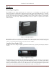
Headstage Requirements
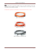
The high input impedance and low bias current of the Amplifier inputs make it possible to connect microelectrodes
with 20 kΩ (at 1kHz) or lower impedance values directly to the Amplifier inputs without the need for a headstage.
This configuration has the advantage of avoiding noise added to the signals by the headstage, but it makes the
application more susceptible to environmental electromagnetic noise. To minimize environmental noise, it is
recommended to keep direct electrode connections shorter than 20 cm (8 inches). For longer connections, headstages
from Blackrock Microsystems are recommended. Headstages allow microelectrodes with impedances up to 5-MΩ
(at 1kHz), and cables up to 6 feet in length.
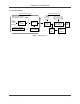
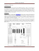
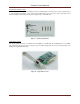
ICS Connectors
The HSF-32 is built to work with Samtec (www.samtec.com) connectors and it is designed to mate with the ICS
family of array holders from Blackrock Microsystems. If you are using an ICS array holder without a headstage, you
will need to use a HBA-32 headstage bypass adaptor instead. To use the ICS-96, you will need a group of three
CHA-32 adapters that are mounted together with a shared reference. To select Ref 1 or Ref 2 on the ICS-96, place a
reference jumper on the CHA-32 board connected to Bank A or Bank C. To select Ground as reference, place a
jumper on CHA-32 board connected to Bank B.
The connector board has up to four Samtec FTSH 36-pin connectors; pins 1-32 are the electrodes, pin 33 is the
reference, pins 34 and 35 is ground, and pin 36 is bus. It can be connected to either unity gain (1x amplification)
headstage followers (HSF-32 – Blackrock Part #4078 or equivalent) or Headstage bypass adapter boards (HBA-32 –
Blackrock Part #4103) and then connected to the inputs of the Amplifier with Samtec ribbon cables; Bank A to A,
Bank B to B, etc.
Figure 8 - Headstage Assembly and Connections