Instruction Manual Bedienungsanleitung Manuel d’utilisation Manuale di Istruzioni RTF READY-TO-FLY
NOTICE All instructions, warranties and other collateral documents are subject to change at the sole discretion of Horizon Hobby, Inc. For up-to-date product literature, visit horizonhobby.com and click on the support tab for this product.
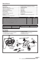
Table of Contents First Flight Preparation .....................................................4 Flying Checklist ...............................................................4 Charging Warnings...........................................................4 Installing the Landing Gear ..............................................5 Installing the Transmitter Batteries (RTF) ..........................5 Installing the Flight Battery ..............................................
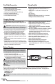
First Flight Preparation Flying Checklist • Remove and inspect contents • Begin charging the flight battery • Install the flight battery in the quadcopter (once it has been fully charged) • Program your computer transmitter (BNF only) • Bind your transmitter (BNF only) • Familiarize yourself with the controls • Find a suitable area for flying ❏ Always turn the transmitter on first ❏ Plug the flight battery into the lead from the 5-in-1 control unit ❏ Allow the 5-in-1 control unit to initialize and arm properl
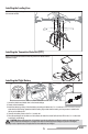
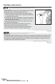
Installing the Landing Gear Install the landing gear using the four included screws. Installing the Transmitter Batteries (RTF) Replace the transmitter batteries when the power LED flashes and the transmitter beeps. Installing the Flight Battery 1 2 3 4 1. Lower the throttle and throttle trim to the lowest settings. 2. Power on the transmitter. 3. Install the battery by sliding it into the battery mounting slot below the 5-in-1 control unit.
Transmitter and Receiver Binding To bind or re-bind your quadcopter to your chosen transmitter, please follow the directions below. General Binding Procedure 1. Disconnect the flight battery from the quadcopter. 2. Select a clean model memory on your transmitter (computer radios only). 3. Select Acro or Airplane model type on your transmitter. 4. Make sure all servo reversing is set to Normal on your transmitter. 5. Center all trims on your transmitter. 6.
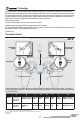
™ Technology Revolutionary SAFE™ (Sensor Assisted Flight Envelope) technology uses an innovative combination of multi-axis sensors and software that allows model aircraft to know its position relative to the horizon. This spatial awareness is utilized to create a controlled flight envelope the aircraft can use to maintain a safe region of bank and pitch angles so you can fly more safely.
Flight Mode and Rate Selection RTF Change flight modes by moving the three-position flight mode switch. Ensure the flight mode switch is in the desired position before flying. • In stability low angle mode (switch position 0), the controls provide a minimum bank angle. This mode is shown by the flight control board on the quadcopter glowing solid blue. • In stability high angle mode (switch position 1), the controls provide for a maximum bank angle.
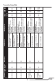
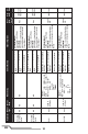
N/A N/A MLP4DSM MLP6DSM 9 N/A N/A DX4e (Old) w/ 2 Position N/A Switch DX5e (Old) w/ 2 Position N/A Switch N/A N/A Model Reverse Type Setup Transmitter N/A N/A N/A N/A Mode Setup Still Mode(Default) Press Trainer = Take Picture Video Mode Press Trainer = Start/Stop Recording Press & Hold Trainer for 4 Seconds = Change Modes Channel 5 (0) = Stability Mode, Low Angle Channel 5 (1) = Agility Mode ACT/AUX (ON) = Agility Mode Still Mode(Default) Press Trainer = Take Picture Video Mode Press T
EN 10 Acro Acro DX6i DX7/7SE N/A DX5e (New) w/ 3 Position N/A Switch N/A N/A Mode Setup Travel Adj: GEAR (0)↑ 100%; GEAR (1) ↑40% MIX 1: FLAP → Gear OFF/ON FLAP - R (6) RATE → -50% All Others - N 0% SW: MIX OFFSET: 0 Travel Adj: GEAR (0)↑ 100%; F MODE (1) ↓40% FLAPS: Norm ←↑100; LAND ↓100 GEAR - R MIX 1: ACT; Gear → Gear ACT All Others - N RATE D 0% U + 100% SW MIX TRIM INH N/A Model Reverse Type Setup DX4e (New) w/ 3 Position N/A Switch Transmitter GEAR (1); Mix (1) = Agility Mode GEAR (1
EN Acro Acro DX8 DX9/DX18 Acro Mode Setup Channel Assign: NEXT 1-4: N/A AUX1 - R 5 Gear: B All Others - N 6 AUX1: I 7-10: Inh Switch Select: AUX1 - R Trainer to Aux 1 All Others - N F Mode to Gear All Others to Inh Switch Select: Trainer to Aux 1; F Mode to Gear Set All Others to Inh MIX 1: GER > GER AUX1 - R RATE: 0% All Others - N -100% OFFSET: 0%; TRIM: Inh SW: Mix0 Model Reverse Type Setup DX7S Transmitter B (2) = Agility Mode B (1) = Stability Mode, High Angle B (0) = Stability Mode,
LED Codes Equipment LED Color Blue Quadcopter Red Red and Blue RTF Transmitter Red LED Status Rapid Blink Solid Slow Blink Solid Solid Blink Blink Solid Operation Bind Mode Stability Mode low angle Stability Mode high angle Agility Mode Low Battery Loss of RF/TX Off Low Rate Hi Rate Understanding the Primary Flight Controls If you are not familiar with the controls of your 180 QX HD, take a few minutes to familiarize yourself with them before attempting your first flight.
Flying the 180 QX HD Takeoff Increase the throttle until the model is approximately 2 ft. (600mm) off the ground and check the trim so the model flies as desired. Once the trim is adjusted, begin flying the model. Typical flight times for the included battery range from 5 to 10 minutes. Low Voltage Cutoff (LVC) LVC decreases the power to the motors when the battery voltage gets low.
Installation 1. Install the included hook and loop tape on the bottom of the camera, as shown. 2. Install the camera on the model using the included hook and loop strap. 3. Connect the servo lead from the main board to the camera servo lead port. If the camera does not function through the transmitter after connection, disconnect the lead, rotate the connector and reconnect it so the lead is in the reverse orientation. 4. Press the camera power button.
Troubleshooting Guide Problem Quadcopter control response is inconsistent or requires extra trim to neutralize movement. Quadcopter will not respond to throttle. Quadcopter does not function and smells burnt after connecting the flight battery. Quadcopter has reduced flight time or is underpowered. LED on receiver flashes rapidly and aircraft will not respond to transmitter (during binding). LED on the receiver flashes rapidly and the quadcopter will not respond to the transmitter (after binding).
Exploded View 12 4 11 16 9 8 3 2 5 8 7 6 15 13 14 2 10 9 1 Parts Listings Part # Description Part # 1 BLH3506 2 BLH3515, EFLH2215 3 BLH7401 4 5 6 7 BLH7402 BLH7403 BLH7404 BLH7502 8 BLH7503 9 BLH7504 Main Gear: BMSR/X, mCP X, mQX Outer Shaft Bearing 3 x 6 x 2mm(2): BMCX/2/MSR/X, FHX, MH-35, MCP X, mQX 5-in-1 Control Unit, RX/ESCs/Mixer/ Gyros/Camera Control: 180 QX HD Canopy: 180 QX HD 5-in-1 Mounting Frame: 180 QX HD Landing Gear 180 QX HD Thruster Boom with Wiring (2): mQX Motor w
Limited Warranty questions and service you in the event that you may need any assistance. For questions or assistance, please visit our website at www.horizonhobby.com, submit a Product Support Inquiry, or call the toll free telephone number referenced in the Warranty and Service Contact Information section to speak with a Product Support representative.
Warranty and Service Contact Information Country of Purchase United States of America Horizon Hobby Contact Information Horizon Service Center (Repairs and Repair Requests) servicecenter.horizonhobby. com/RequestForm/ www.quickbase.com/db/ bghj7ey8c?a=GenNewRecord 888-959-2304 sales@horizonhobby.com 888-959-2304 sales@horizonhobby.co.
Compliance Information for the European Union Declaration of Conformity Declaration of Conformity (in accordance with ISO/IEC 17050-1) No. HH2013091401 Product(s): 180 QX HD BNF Item Number(s): BLH7480 Equipment class: 1 The object of declaration described above is in conformity with the requirements of the specifications listed below, following the provisions of the European R&TTE directive 1999/5/EC, EMC Directive 2004/108/EC and LVD Directive 2006/95/EC: EN 301 489-1 V1.9.2: 2012 EN 301 489-17 V2.1.
©2013 Horizon Hobby, Inc Blade, E-flite, SAFE, DSM, DSM2, DSMX, the BNF logo, ModelMatch and the Horizon Hobby logo are trademarks or registered trademarks of Horizon Hobby, Inc. The Spektrum trademark is used with permission of Bachmann Industries, Inc. Futaba is a registered trademark of Futaba Denshi Kogyo Kabushiki Kaisha Corporation of Japan. All other trademarks, service marks or logos are property of their respective owners. Patents pending. Created 12/13 41864.