Instruction Manual Bedienungsanleitung Manuel d’utilisation Manuale di Istruzioni RTF
NOTICE All instructions, warranties and other collateral documents are subject to change at the sole discretion of Horizon Hobby, LLC. For up-to-date product literature, visit horizonhobby.com and click on the support tab for this product.
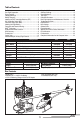
Table of Contents Box Contents .................................................................... 3 First Flight Preparation ...................................................... 4 Flying Checklist ................................................................ 4 Charging Warnings............................................................ 4 Battery Charging............................................................... 4 Installing the DXe Transmitter Batteries (RTF) ....................
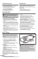
First Flight Preparation Flying Checklist • • • • ❏ Always turn the transmitter on first ❏ Plug the flight battery into the lead from the ESC ❏ Allow the receiver and ESC to initialize and arm properly ❏ Fly the model ❏ Land the model ❏ Unplug the flight battery from the ESC ❏ Always turn the transmitter off last Remove and inspect contents Begin charging the flight battery Program your computer transmitter (BNF only) Install the flight battery in the helicopter (once it has been fully charged) • Bind your t
Installing the DXe Transmitter Batteries (RTF) The LED indicator flashes and the transmitter beeps progressively faster as the battery voltage drops. Replace the transmitter batteries when the transmitter begins to beep.
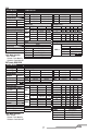
Transmitter Setup Table (BNF) DX6i SETUP LIST ADJUST LIST Model Type HELI 1 servo Normal Swash Type REVERSE Channel THRO AILE ELEV RUDD GYRO PITC Direction N N N N N R Modulation Type AUTO DSMX-ENABLE D/R COMBI D/R SW Timer Down Timer Switch AILE 5:00 THR CUT TRAVEL ADJ Channel THRO AILE ELEV RUDD GYRO PITC D/R & Expo Chan Sw Pos 0 AILE 1 0 ELEV 1 0 RUDD 1 Travel 100/100 100/100 100/100 100/100 100/100 100/100 GYRO RATE SW-F.
DX6 FUNCTION LIST SYSTEM SETUP Model Type Swash Type HELI Normal F-Mode Setup Switch 1 Switch B Switch 2 Inhibit Hold Switch Switch H Channel Assign Channel Input Config 1 Throttle 2 Aileron 3 Elevator 4 Rudder 5 Flight Mode Switch B 6 Collective Frame Rate 11ms DSMX Panic Mode Operation Bind / I Button Pressed = Panic Mode On Released = Panic Mode Off Servo Setup Chan Travel THR 100/100 AIL 100/100 ELE 100/100 D/R & Expo Chan Sw (F) Pos 0 AILE 1 0 ELEV 1 0 RUDD 1 Reverse Normal Normal Normal D/R 100/10
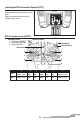
Installing the Flight Battery 1 2 3 1. Lower the throttle stick to the lowest position. 2. Power ON the transmitter. 3. Center all trims. For the included Spektrum DXe transmitter (RTF only), the trims are centered when you hear a higher pitched beep while pressing the trim button. Move the trim in both directions until you hear the high-pitched beep. 4. Attach the hook material to the helicopter frame and the loop material to the flight battery. 5. Install the flight battery on the helicopter frame.
Your RTF transmitter comes prebound to the model. If you need to re-bind, follow the directions below. RTF DXe Binding Procedure 1. Disconnect the flight battery from the helicopter. 2. Lower the throttle stick to the lowest position. Set all trims to the center position. 3. Power off the transmitter. 4. Install the bind plug in the receiver BIND/PROG port (far left side of the receiver). 5. Connect the flight battery to the ESC. The receiver LED flashes, indicating it is in bind mode. 6.
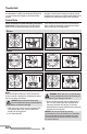
Throttle Hold Throttle hold is used to prevent the motor from powering on inadvertently. For safety, turn throttle hold ON any time you need to touch the helicopter or check the direction controls. Throttle hold is also used to turn off the motor quickly if the helicopter is out of control, in danger of crashing, or both. The blades will continue to spin briefly when throttle hold is activated. Pitch and direction control is still maintained.
Understanding the Primary Flight Controls If you are not familiar with the controls of your 230 S, take a few minutes to familiarize yourself with them before attempting your first flight.
Flying the 230 S Consult your local laws and ordinances before choosing a location to fly your aircraft. We recommend flying your aircraft outside in calm winds or inside a large gymnasium. Always avoid flying near houses, trees, wires and buildings. You should also be careful to avoid flying in areas where there are many people, such as busy parks, schoolyards or soccer fields. It is best to fly from a smooth flat surface as this will allow the model to slide without tipping over.
4. Cyclic Response (Default 100%) Higher cyclic response will result in a more aggressive cyclic response. Lower cyclic response will result in a less aggressive cyclic response. 5. Tailrotor P Gain Adjustment (Default 100%) Higher gain will result in greater stability. Setting the gain too high may result in random twitches if your model has an excessive level of vibration. High frequency oscillations may also occur if the gain is set too high. Lower gain may result in a decrease in stability.
The current gain value for the selected parameter is indicated on the Flight Log screen and by the angle of the swashplate (forward or backward) as shown in the table at the right. Move the cyclic stick forward or backward to adjust the gain value. Moving the stick forward will increase the gain value. Moving the stick backward will decrease the gain value. It is always best to adjust one gain at a time. Make small adjustments (5% or less) and test fly the model to evaluate the adjustments that were made.
Trim Flight Perform this procedure if the model is not performing well or has been recently rebuilt from a crash. The trim flight procedure was performed during the factory test flight and only needs to be performed if you notice the model is not returning to level consistently or if the model does not remain still during stationary pirouettes. The trim flight is used to determine the optimal settings for SAFE® technology during flight. The trim flight must be performed in calm conditions.
Calibration Procedure If the Blade 230 S is experiencing drift issues after completing the trim flight procedure located at www.bladehelis.com, perform the following calibration. The calibration procedure may also be needed following crash repairs. To perform the calibration procedure below, the Spektrum™ AR636 receiver installed in the Blade 230 S must have the most recent firmware. Receiver firmware updates and instructions are available under “PC Firmware Updates” at www.spektrumrc.com/technology/AS3X.aspx.
Post-Flight Inspection and Maintenance Checklist √ Make sure the plastic ball link holds the control ball, but is not tight (binding) on the ball. When a link is too loose on the ball, it can separate from the ball during flight and cause a crash. Replace worn ball links before they fail. Make sure the battery is not connected before cleaning. Remove dust and debris with a soft brush or Cleaning a dry, lint-free cloth.
Problem Possible Cause Solution The bind plug was not removed from the receiver after binding Less than a 5-second wait between first powering on the transmitter and connecting the LED on the receiver flashes flight battery to the helicopter rapidly and the helicopter The helicopter is bound to a will not respond to the different model memory transmitter (after binding) (ModelMatch™ transmitters only) Flight battery or transmitter battery charge is too low Aircraft or transmitter is too close to large metal
Exploded View 3 27 20 4 29 1 11 30 22 21 2 7 14 12 31 8 16 19 9 23 24 10 15 5 22 33 13 28 18 6 7 17 26 10 30 25 11 11 Parts Listings 1 2 3 4 5 6 7 8 9 10 Part # BLH1500 BLH1580 BLH1501 BLH1502 BLH1503 BLH1504 BLH1505 BLH1506 BLH1507 BLH1508 BLH1509 BLH1510 11 BLH1511 12 13 14 15 16 BLH1512 BLH1513 BLH1514 BLH1515 BLH1516 Description 230 S RTF 230 S BNF Main rotor head Blade 230s Spindle set Blade 230s Main rotor blade set Blade 230s Main rotor head linkage set Blade 230s Sw
Optional Parts Part # Description BLH1574 BLH1575 BLH1576 BLH1577 SPMA3065 Canopy fiberglass (green) Blade 230s Canopy fiberglass (orange) Blade 230s Main rotor blade set (green)t Blade 230s Main rotor blade set (orange) Blade 230s AS3X Programming Cable - USB Interface DX6i DSMX 6-Channel Transmitter Only Part # Description DX7s DSMX 7-Channel Transmitter Only DX6 DSMX 6-Channel Transmitter Only DX7 DSMX 7-Channel Transmitter Only DX8 DSMX 8-Channel Transmitter Only DX9 DSMX 9-Channel Transmitter Only D
Warranty Requirements For Warranty consideration, you must include your original sales receipt verifying the proof-of-purchase date. Provided warranty conditions have been met, your Product will be serviced or replaced free of charge. Service or replacement decisions are at the sole discretion of Horizon.
FCC Information This device complies with part 15 of the FCC rules. Operation is subject to the following two conditions: (1) This device may not cause harmful interference, and (2) this device must accept any interference received, including interference that may cause undesired operation. CAUTION: Changes or modifications not expressly approved by the party responsible for compliance could void the user’s authority to operate the equipment.
©2016 Horizon Hobby, LLC Blade, E-flite, Bind-N-Fly, the BNF logo, DSM, DSM2, DSMX, AS3X, SAFE, the SAFE logo and ModelMatch are trademarks or registered trademarks of Horizon Hobby, LLC. The Spektrum trademark is used with permission of Bachmann Industries, Inc. Futaba is a registered trademark of Futaba Denshi Kogyo Kabushiki Kaisha Corporation of Japan All other trademarks, service marks and logos are property of their respective owners. Patents pending. Created 11/15 45598.