
User Manual


1
Blade
®
230 S RTF/BNF Helicopter Advanced Settings
The default receiver settings are appropriate for most users. We recommend fl ying with the
default parameters before making any adjustments.
WARNING: To ensure your safety, always disconnect the motor wires from the ESC
before performing the following steps. After you have completed the adjustments,
reconnect the motor wires to the ESC before attempting to fl y the model.
Gain Parameters
1. Cyclic P Gain Adjustment (Default 100%)
Higher gain will result in greater stability. Setting the gain too high may result in random
twitches if your model has an excessive level of vibration. High frequency oscillations may
also occur if the gain is set too high.
Lower gain will result in less stability. Too low of a value may result in a less stable model,
particularly outdoors in winds.
If you are located at a higher altitude or in a warmer climate, higher gains may be benefi -
cial—the opposite is true for lower altitude or colder climates.
2. Cyclic I Gain Adjustment (Default 100%)
Higher gain will result in the model remaining still, but may cause low frequency oscillations
if increased too far.
Lower gain will result in the model drifting slowly.
If you are located at a higher altitude or in a warmer climate, higher gains may be benefi -
cial—the opposite is true for lower altitude or colder climates.
3. Cyclic D Gain Adjustment (Default 100%)
Higher gain will improve the response rate of your inputs. If the gain is raised too much, high
frequency oscillations may occur.
Lower gain will slow down the response to inputs.
4. Cyclic Response (Default 100%)
Higher cyclic response will result in a more aggressive cyclic response.
Lower cyclic response will result in a less aggressive cyclic response.
5. Tailrotor P Gain Adjustment (Default 100%)
Higher gain will result in greater stability. Setting the gain too high may result in random
twitches if your model has an excessive level of vibration. High frequency oscillations
may also occur if the gain is set too high.
Lower gain may result in a decrease in stability. Too low of a value may result in a less
stable model, particularly outdoors in winds.
If you are located at a higher altitude or in a warmer climate, higher gains may be benefi -
cial—the opposite is true for lower altitude or colder climates.
6. Tailrotor I Gain Adjustment (Default 100%)
Higher gain results in the tail remaining still. If the gain is raised too far, low speed oscilla-
tions may occur.
Lower gain will result in the tail drifting in fl ight over time.
If you are located at a higher altitude or in a warmer climate, higher gains may be benefi -
cial—the opposite is true for lower altitude or colder climates.
7. Tailrotor D Gain Adjustment (Default 100%)
Higher gain will improve the response rate to your inputs. If raised too far, high frequency
oscillations may occur.
Lower gain will slow down the response to inputs, but will not have an effect on stability.
8. Tailrotor Adaptive Filtering
Higher gain will reduce oscillations during high speed fl ight and when using large amounts
of collective.
Lower gain will improve tail performance but may lead to tail oscillations.
Once you have entered Gain Adjustment Mode, move the cyclic stick right and left to select
the gain parameter to adjust. Moving the stick right will select the next parameter. Moving
the stick left will select the previous parameter.
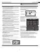
The selected gain parameter
is indicated on the Flight Log
screen above and by the lean
of the swashplate on the roll
axis as shown in the table at
the right.
The current gain value for the
selected parameter is indicated
on the Flight Log screen and
by the angle of the swashplate
(forward or backward) as shown
in the table at the right.
Move the cyclic stick forward
or backward to adjust the gain
value. Moving the stick forward will increase the gain value. Moving the stick backward will
decrease the gain value.
It is always best to adjust one gain at a time. Make small adjustments (5% or less) and test
fl y the model to evaluate the adjustments that were made.
If you would like to reset the current gain value to the default value of 100%, move and hold
the rudder stick full right for 1 second. The swash will level on the pitch axis, indicating a
100% gain setting.
Saving the Gain Adjustments
1. Lower the throttle stick to the lowest position and release the sticks.
2. Press and hold switch I until the swash servos move.
3. Release switch I to save the gain adjustments.
4. Reconnect the main drive motor to the ESC. Your model is now ready for fl ight.
Parameter #
Display
location
Swash Position Page #
1 A 100% to the Left 1
2 B 70% to the Left 1
3 L 40% to the Left 1
4 R 10% to the Left 1
5 A 10% to the Right 2
6 B 40% to the Right 2
7 L 70% to the Right 2
8 R 100% to the Right 2
Entering Gain Adjustment Mode
1. Lower the throttle stick to the lowest position.
2. Power ON the transmitter.
3. Install the fl ight battery on the helicopter frame, securing it with the hook and loop strap.
4. Connect the battery connector to the ESC.
5. Place the helicopter on a fl at surface and leave it still until the orange receiver LED glows
solid, indicating initialization is complete.
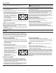
6. Move and hold both transmitter sticks to the
bottom right corner as shown.
7. Press and hold the bind/panic switch until the
swash servos move.
8. Release the sticks and the bind/panic switch.
The model is now in Gain Adjustment Mode.
9. Proceed to Adjusting the Gain Values to make any desired changes.
Adjusting the Gain Values
If you are using a Spektrum
™
telemetry-enabled transmitter, the gain adjustments can be
viewed on the Flight Log screen. Refer to your transmitter instructions to locate this screen.
The gain parameter currently selected will fl ash on the transmitter screen. If you are not
using a Spektrum telemetry-enabled transmitter, the parameter and gain values are indicated
by the position of the swashplate on the helicopter.
P age number
1 = Cyclic gains
2 = Tail rotor gains
Gain parameter
selected
Gain value
display location
Flight Log Screen
Swash Position Gain Value
Full backward 0%
50% backward 50%
Level forward and backward 100%
50% forward 150%
Full forward 200%
EN