Instruction Manual Bedienungsanleitung Manuel d’utilisation Manuale di Istruzioni RTF READY-TO-FLY
NOTICE All instructions, warranties and other collateral documents are subject to change at the sole discretion of Horizon Hobby, LLC. For up-to-date product literature, visit horizonhobby.com and click on the support tab for this product.
Table of Contents Box Contents ..................................................................... 3 First Flight Preparation ....................................................... 4 Flying Checklist.................................................................. 4 Charging Warnings............................................................. 4 Battery Charging ................................................................ 4 Installing the Transmitter Batteries (RTF) ..............................
First Flight Preparation Flying Checklist • • • • • ❏ Always turn the transmitter on first ❏ Plug the flight battery into the lead from the ESC ❏ Allow the receiver and ESC to initialize and arm properly ❏ Fly the model ❏ Land the model ❏ Unplug the flight battery from the ESC ❏ Always turn the transmitter off last Remove and inspect contents Begin charging the flight battery Install the batteries in the transmitter (RTF only) Program your computer transmitter (BNF only) Install the flight battery in the hel
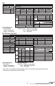
Installing the Transmitter Batteries (RTF) Replace the transmitter batteries when the transmitter beeps. Transmitter Setup (BNF) Program your transmitter before attempting to bind or fly the helicopter. Transmitter programming values are shown below for the Spektrum DX6i, DX7s, DX6, DX7, DX8, DX9 and DX18. The files for models using Spektrum™ transmitters with Spektrum AirWare™ software are also available for download online at www.spektrumrc.com.
DX6i SETUP LIST ADJUST LIST Model Type REVERSE Channel THRO AILE ELEV RUDD GEAR FLAP Acro Direction N N N N R N Modulation Type AUTO DSMX-ENABLE D/R COMBI D/R SW TRAVEL ADJ Channel THRO AILE ELEV RUDD GEAR PITC Travel 100/100 100/100 100/100 100/100 100/100 100/100 D/R & Expo Chan Sw Pos 0 AILE 1 0 ELEV 1 0 RUDD 1 FLAPS FLAP 100 100 NORM LAND ELEV 0 0 AILE Timer Down Timer 5:00 Switch THR CUT Panic Mode Operation Gyro Switch: Pos 0 = Panic Mode Off Pos 1 = Panic Mode On D/R 100 75 100 75 100 75
DX8 SYSTEM SETUP FUNCTION LIST Servo Setup Chan Travel Reverse Chan Travel Reverse THR 100/100 Normal GER 100/100 Normal Aux 1 AIL 100/100 Normal AX1 100/100 Reverse Gear ELE 100/100 Normal AX2 100/100 Normal INH RUD 100/100 Normal D/R & Expo D/R & Expo Chan Switch Pos (AIL D/R) D/R Expo* Chan Switch Pos (AIL D/R) D/R Expo* 0 100/100 0 0 100/100 0 1 100/100 0 1 100/100 0 AILE RUDD 2 75/75 0 2 75/75 0 0 100/100 0 Timer ELEV 1 100/100 0 Mode Count Down 2 75/75 0 Time 5:00 Tone Throttle Cut Start Throttle Ou
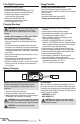
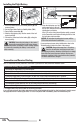
Installing the Flight Battery A B C 1. Lower the throttle stick to the lowest position (A) and center all trims. 2. Set the Flight Mode Switch to Stability Mode (FM0) 3. Power ON the transmitter (B). 4. Slide the flight battery fully into the mount of the helicopter frame (C). 5. Connect the power lead to the battery (D), noting the correct polarity. 6.
To bind or re-bind your helicopter to your chosen transmitter, follow the directions below. General Binding Procedure (BNF) 1. Disconnect the flight battery from the helicopter. 2. Refer the Transmitter Setup Table to correctly setup your transmitter. 3. Lower the throttle stick to the lowest position and center all trims on your transmitter. 4. Power off the transmitter and move all switches to the 0 position. Move the throttle to the low/off position. 5. Connect the flight battery to the control board.
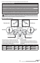
Control Tests Test the controls prior to the first flight to ensure the servos, linkages and parts operate correctly. Ensure the throttle is in the low position when doing the control tests. Elevator Left Side View Left Side View Elevator up Elevator down Aileron Rear View Rear View Aileron right Aileron left Understanding the Primary Flight Controls If you are not familiar with the controls of your 120 S, take a few minutes to familiarize yourself with them before attempting your first flight.
® Technology ® Revolutionary SAFE (Sensor Assisted Flight Envelope) technology uses an innovative combination of multi-axis sensors and software that allows model aircraft to know its position relative to the horizon. This spatial awareness is utilized to create a controlled flight envelope the aircraft can use to maintain a safe region of bank and pitch angles so you can fly more safely.
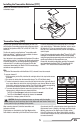
Drift Calibration The helicopter has been calibrated in the factory before shipment, but it is possible that a crash will cause mechanical distortion of the frame, resulting in a slight drift in Stability mode. In this situation, please follow the calibration procedure. Before beginning the calibration procedure, fully charge the flight battery and ensure the helicopter and transmitter are bound properly, per the binding instructions. To Calibrate the Blade 120 S: 1.
Problem Possible Cause Solution Flight battery charge is low Helicopter has reduced flight time or is underpowered Flight battery is damaged Flight conditions might be too cold Transmitter too near aircraft during binding process LED on receiver flashes rapidly and aircraft will not Bind switch or button was not held respond to transmitter (during while transmitter was powered on binding) Aircraft or transmitter is too close to large metal object, wireless source or another transmitter Less than a 5-seco
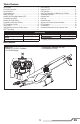
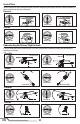
Exploded View 11 15 18 20 22 22 13 18 26 15 8 25 23 7 19 4 14 10 9 21 2 1 14 24 3 21 5 6 16 12 17 Parts List 1 2 3 4 5 6 7 8 9 10 11 12 13 14 EN Part # Description BLH4100 BLH4180 SPMSH2029L SPMSH2030L BLH4101 BLH4102 BLH4103 BLH4104 BLH4105 BLH4106 BLH4107 BLH4108 BLH4111 BLH4112 BLH3117 BLH3705 120 S RTF 120 S BNF Linear Long, 35mm lead Linear Long, 60mm lead Main Control Board Tail Boom Set Main Motor Main Frame Main Shaft w/hardware Swashplate Canopy Tail Fin Main Blades w
Limited Warranty What this Warranty Covers Horizon Hobby, LLC, (Horizon) warrants to the original purchaser that the product purchased (the “Product”) will be free from defects in materials and workmanship at the date of purchase.
Warranty and Service Contact Information Country of Purchase United States of America Horizon Hobby Horizon Service Center (Repairs and Repair Requests) Horizon Product Support (Product Technical Assistance) Sales European Union Horizon Technischer Service Sales: Horizon Hobby GmbH Contact Information servicecenter.horizonhobby.com/ RequestForm/ productsupport@horizonhobby.com 877-504-0233 websales@horizonhobby.com 800-338-4639 service@horizonhobby.
IC Information IC: 6175A-BRWDXMT 6157A-GEN1AR6400H This device complies with Industry Canada license-exempt RSS standard(s). Operation is subject to the following two conditions: (1) this device may not cause interference, and (2) this device must accept any interference, including interference that may cause undesired operation of the device.
HINWEIS Alle Anweisungen, Garantien und anderen zugehörigen Dokumente können im eigenen Ermessen von Horizon Hobby, LLC jederzeit geändert werden. Die aktuelle Produktliteratur finden Sie auf horizonhobby.com unter der Registerkarte „Support“ für das betreffende Produkt.
Inhaltsangabe Lieferumfang ............................................................. 19 Vorbereitung für den Erstflug ...................................... 20 Checkliste zum Fliegen ............................................... 20 Akku-Warnhinweise ................................................... 20 Laden des Flugakkus ................................................. 20 Einsetzen der Senderbatterien (RTF) ............................ 21 Sendereinstellungen (BNF) ...................................
Vorbereitung für den Erstflug Checkliste zum Fliegen • • • • • • • • ❏ Schalten Sie immer den Sender zuerst ein ❏ Stecken Sie den Flugakku an den Anschluß der ESC ❏ Lassen Sie der ESC Kontrolleinheit Zeit zum initialisieren und armieren ❏ Fliegen Sie das Modell ❏ Landen Sie das Modell ❏ Stecken Sie den Flugakku von der ESC ❏ Schalten Sie immer den Sender als letztes aus Entnehmen und überprüfen Sie die Komponenten Laden Sie den Flugakku Setzen Sie die Batterien in den Sender ein (nur RTF Version) Program
Einsetzen der Senderbatterien (RTF) Ersetzen Sie die Sender Batterien wenn die der Sender piept. Sendereinstellungen (BNF) Sie müssen Ihren Sender zuerst programmieren, bevor Sie den Helikopter binden oder fliegen können. Die Werte, die Sie zum Programmieren Ihres Senders für Spektrum DX6i, DX7s, DX6, DX7, DX8, DX9 und DX18 Empfänger benötigen, sind unten angeführt. Die Spektrum-Modelldateien für Spektrum AirWare Sender stehen auch online in der Spektrum Community zum Download zur Verfügung.
DX6i SETUP LIST Model Type REVERSE Channel THRO AILE ELEV RUDD GEAR FLAP ADJUST LIST Acro Direction N N N N R N Modulation Type AUTO DSMX-ENABLE D/R COMBI D/R SW Timer Down Timer Switch TRAVEL ADJ Channel THRO AILE ELEV RUDD GEAR PITC Travel 100/100 100/100 100/100 100/100 100/100 100/100 D/R & Expo Chan Sw Pos 0 AILE 1 0 ELEV 1 0 RUDD 1 FLAPS NORM LAND FLAP 100 100 ELEV 0 0 AILE 5:00 THR CUT D/R 100 75 100 75 100 75 Expo* INH INH INH INH INH INH Mixing MIX 1 GEAR > GEAR RATE SW ACT ACT D 0% U
DX8 Systemeinstellung Funktionsliste Servoeinstellung Kanal Servoweg Laufrichtung Kanal Servoweg Laufrichtung GAS 100/100 Normal FW 100/100 Normal Aux 1 ROL 100/100 Normal AX1 100/100 Reverse FW NCK 100/100 Normal AX2 100/100 Normal AUS HCK 100/100 Normal D/R & Expo D/R & Expo Kanal Shalter Pos (AIL D/R) D/R Expo* Kanal Shalter Pos (AIL D/R) D/R Expo* 0 100/100 0 0 100/100 0 1 100/100 0 1 100/100 0 ROL HCK 2 75/75 0 2 75/75 0 0 100/100 0 Timer NCK 1 100/100 0 Mode Count Down 2 75/75 0 Time 5:00 Tone Gas A
Einsetzen des Flugakkus A B 1. Bringen Sie den Gashebel auf die unterste Position (A) und zentrieren alle Trimmungen. 2. Stellen Sie den Flugmodeschalter auf den Stabilitätsmode (FM0). 3. Schalten Sie den Sender ein (B). 4. Schieben Sie vorsichtig den Flugakku in den Halter am Hubschrauberrahmen (C). 5. Schließen Sie den Akkustecker am Akku an und achten dabei auf die korrekte Polarität (D). ACHTUNG: Der verpolte Anschluss des Akkus an den Regler beschädigt den Regler, Akku oder beides.
Um ihren Hubschrauber an den gewählten Sender zu binden oder neu zu binden folgen Sie bitte den untenstehenden Anweisungen. Der Bindevorgang (BNF) 1. Trennen Sie den Flugakku vom Hubschrauber. 2. Entnehmen Sie aus der Sendereinstelltabelle die korrekte Einstellung für ihren Sender. 3. Bringen Sie den Gashebel auf die unterste Position und zentrieren alle Trimmungen auf dem Sender. 4. Schalten Sie den Sender aus und alle Schalter in die 0 Position. Stellen Sie das Gas in die Niedrig / Motor Aus Position. 5.
Kontrolltests Testen Sie vor dem Erstflug die Kontrollen um sicher zustellen, dass die Servos, Anlenkungen und weitere Teile richtig arbeiten. Versichern Sie sich, dass das Gas in der niedrigsten Position bei dem Durchführen dieser Tests ist.
® Technologie Die revolutionäre SAFE Technologie von Horizon Hobby (Sensor Assited Flight Envelope) verwendet eine innovative Kombination aus Multi-Achs Sensoren und Software, die es erlauben, die relative Position des Fluggerätes im Raum jederzeit zu bestimmen. Diese dreidimensionale Wahrnehmung schafft eine schräglagenbegrenzte Fluglage die Sie sicherer Fliegen läßt. Dabei werden Roll- und Nickwinkel beeinflusst und geregelt, um die Flugsicherheit zu erhöhen.
Stabilitätsmode mit großen Neigewinkel (FM1): Die Empfänger LED leuchtet blau. In diesen Flugmode sind größere Neigewinkel und höhere Fluggeschwindigkeiten möglich. Wird die zyklische (Taumelscheiben) Steuerung losgelassen richtet sich das Modell von selbst wieder auf. Agilitätsmode (FM2): Die Empfänger LED leuchtet rot. Der mögliche Neigewinkel ist nicht begrenzt. Wird die zyklische (Taumelscheiben) Steuerung losgelassen richtet sich das Modell nicht von selbst wieder auf.
Problem Mögliche Ursache Lösung Trennen Sie den Flugakku, bringen Sie den Gashebel in die niedrigste Postion und stellen die Gastrimmung ein paar Klicks nach unten. Schließen Sie den Flugakku an und lassen sich das Modell Hubschrauber reagiert nicht initialisieren auf Gas Hubschrauber wurde während der Initia- Trennen Sie den Flugakku und initialisieren den Hubschrauber lisierung bewegt erneut.
Problem Mögliche Ursache Lösung Driftet bei Wind Normal Schwere Vibrationen Drehende Komponente ist nicht mehr gewuchtet Das Modell driftet mit dem Wind sollte aber dabei aufrecht bleiben. Steuern Sie mit der zyklischen Steuerung in die entsprechenden Richtung um das Modell auf einem Punkt zu halten. Das Modell muß sich dabei etwas gegen den Wind lehnen sonst wird er wieder vom Wind abgetrieben Prüfen Sie die Hauptrotorwelle, Heckrotor, Hauptrotorblätter, Rahmen und Adapter auf Beschädigungen.
Garantie und Service Informationen Warnung Ein ferngesteuertes Modell ist kein Spielzeug. Es kann, wenn es falsch eingesetzt wird, zu erheblichen Verletzungen bei Lebewesen und Beschädigungen an Sachgütern führen. Betreiben Sie Ihr RC-Modell nur auf freien Plätzen und beachten Sie alle Hinweise der Bedienungsanleitung des Modells wie auch der Fernsteuerung. Garantiezeitraum Exklusive Garantie Horizon Hobby LLC (Horizon) garantiert, dass dasgekaufte Produkt frei von Material- und Montagefehlern ist.
Garantie und Service Kontaktinformationen Land des Kauf Europäische Union Horizon Hobby Telefon/E-mail Adresse Horizon Technischer Service service@horizonhobby.eu Sales: Horizon Hobby GmbH +49 (0) 4121 2655 100 Adresse Hanskampring 9 D 22885 Barsbüttel, Germany Rechtliche Informationen für die Europäische Union EU Konformitätserklärung RTF: Horizon LLC erklärt hiermit, dass dieses Produkt konform zu den essentiellen Anforderungen der RED, EMC Direktive, und LVD ist.
DE
REMARQUE La totalité des instructions, garanties et autres documents est sujette à modification à la seule discrétion d’Horizon Hobby, LLC. Pour obtenir la documentation à jour, rendez-vous sur le site horizonhobby.com et cliquez sur l’onglet de support de ce produit.
Table des matières Contenu de la boîte .......................................................... 35 Préparation au premier vol................................................ 36 Procédure de vol .............................................................. 36 Avertissements relatifs à la charge .................................... 36 Charge de la batterie ........................................................ 36 Installation des piles de l’émetteur (RTF) ............................
Préparation au premier vol Procédure de vol • • • • • ❏ Mettez toujours l’émetteur sous tension en premier ❏ Branchez la batterie à la prise du contrôleur ❏ Patientez durant l’initialisation du contrôleur ❏ Effectuez votre vol ❏ Faites atterrir le modèle ❏ Débranchez la batterie du contrôleur ❏ Mettez toujours l’émetteur hors tension en dernier Sortez tous les éléments de la boîte et inspectez-les Mettez la batterie en charge Installez les piles dans l'émetteur (RTF seulement) Programmez votre émetteur
Installation des piles de l’émetteur (RTF) Remplacez les piles quand l'émetteur bipe. Réglage de l’émetteur (BNF) Programmez votre émetteur avant d’essayer d’effectuer l’affectation ou de faire voler l’hélicoptère. On trouvera, ci-après, des valeurs de programmation pour les Spektrum DX6i, DX7s, DX6, DX7, DX8, DX9 et DX18. Les fichiers de programme des modèles pour les émetteurs Spektrum utilisant l’interface Spektrum AirWare sont disponibles en ligne sur www.spektrumrc.com.
DX6i LISTE DES PARAMETRES VALEURS Type de modèle Course de servo Voie Gaz Ailerons Profondeur Dérive Gyro Pas Inversion Voie Gaz Ailerons Profondeur Dérive Gyro Volets Acro Direction N N N N R N Type de Modulation AUTO DSMX-ENABLE D/R COMBI D/R SW Double-débattements et Expo Voie Pos. Inter.
DX8 PARAMETRES SYSTEME Type de modèle Sélection interr. Écolage Mode de Vol Les autres ACRO Aux 1 Gear INH LISTE DES FONCTIONS Course des servos Voie Course 100/100 Gaz 100/100 Ailerons 100/100 Profondeur 100/100 Dérive Inversion Normal Normal Normal Normal Voie Gear AX1 AX2 Course 100/100 100/100 100/100 Inversion Normal Inversion Normal Double-débattements et Expo Double-débattements et Expo Voie Interr. Pos (AIL D/R) D/R Expo* Voie Interr.
Installation de la batterie A B C 1. Baissez le manche des gaz à fond (A) et centrez tous les trims. 2. Mettez l'interrupteur Mode de vol sur Mode stabilité (FM0). 3. Mettez l'émetteur sous tension (B). 4. Glissez la batterie de vol complètement chargée dans le châssis de l'hélicoptère (C). 5. Branchez la câble d'alimentation de la batterie (D) en respectant la polarité. ATTENTION: La connexion de la batterie à un contrôleur en inversant la polarité peut endommager le contrôleur, la batterie ou les deux.
Pour affecter ou ré-affecter votre hélicoptère à l'émetteur de votre choix, veuillez suivre les instructions suivantes. Processus général d'affectation (BNF) 1. Déconnectez la batterie de l'hélicoptère. 2. Référez-vous au tableau des paramètres de l'émetteur pour configurer votre émetteur. 3. Baissez le manche des gaz à fond. Mettez tous les trims de votre émetteur au neutre. 4. Mettez l'émetteur hors tension et placez tous les interrupteurs en position 0. Placez le manche des gaz en position basse. 5.
Test des commandes Testez les commandes avant d'effectuer le premier vol pour contrôler les mouvements des servos, des tringleries et autres éléments. Assurez-vous que le manche des gaz est en position basse quand vous effectuez ce test.
® Technologie La technologie révolutionnaire SAFE (Système d'entraînement assisté par capteurs) utilise la combinaison de capteurs sur différents axes et un logiciel permettant au modèle de connaître sa position par rapport à l'horizon. Cette reconnaissance de l'espace est utilisée pour générer un domaine de vol sécurisé en limitant les angles afin de piloter en sécurité.
Correction des déviations L’hélicoptère a été calibré en usine avant l’expédition, mais il est possible qu’un crash entraine une déformation de la structure et donc une légère déviation en mode Stabilité. Dans cette situation, veuillez suivre la procédure de calibration. Avant de commencer la procédure de calibration, assurezvous que les batteries sont complètement chargées et que l'hélicoptère et l'émetteur ont bien été affectés selon les instructions d'affectation. Pour calibrer votre Blade 120 S: 1.
Problème L’hélicoptère ne vole pas très longtemps ou manque de puissance La DEL du module clignote rapidement et l’appareil ne répond pas aux commandes (durant l’affectation) La DEL du module clignote rapidement et le l'hélicoptère ne répond pas aux commandes (après l’affectation) L'hélicoptère vibre ou tremble en vol Le modèle ne reste pas à plat/ ne se remet pas à plat en mode Panique.
Vue éclatée 11 15 18 20 22 22 13 18 26 15 8 25 23 7 19 4 14 10 9 21 2 1 14 24 3 21 5 6 16 12 17 Liste des pièces détachées 1 2 3 4 5 6 7 8 9 10 11 12 13 14 FR Réf.
Garantie et réparations Durée de la garantie Garantie exclusive - Horizon Hobby, LLC (Horizon) garantit que le Produit acheté (le « Produit ») sera exempt de défauts matériels et de fabrication à sa date d’achat par l’Acheteur. La durée de garantie correspond aux dispositions légales du pays dans lequel le produit a été acquis. La durée de garantie est de 6 mois et la durée d’obligation de garantie de 18 mois à l’expiration de la période de garantie.
Coordonnées de Garantie et réparations Pays d’achat Horizon Hobby Numéro de téléphone/E-mail Horizon Technischer Service service@horizonhobby.eu Sales: Horizon Hobby GmbH +49 (0) 4121 2655 100 Union européenne Adresse Hanskampring 9 D 22885 Barsbüttel, Germany Information IC IC: 6175A-BRWDXMT 6157A-GEN1AR6400H Le présent appareil est conforme aux CNR d’Industrie Canada applicables aux appareils radio exempts de licence.
FR
AVVISO Tutte le istruzioni, le garanzie e gli altri documenti pertinenti sono soggetti a cambiamenti a totale discrezione di Horizon Hobby, LLC. Per una documentazione aggiornata sul prodotto, visitare il sito horizonhobby.com e fare clic sulla sezione Support del prodotto.
Indice Contenuto del Kit ............................................................. 51 Preparazione al primo volo................................................ 52 Lista dei controlli prevolo .................................................. 52 Avvertenze e istruzioni per le batterie ................................ 52 Carica della batteria ......................................................... 52 Installazione delle pile nella trasmittente (RTF) ...................
Preparazione al primo volo Lista dei controlli prevolo • • • • • ❏ Accendere sempre prima il trasmettitore ❏ Collegare la batteria di volo al cavo proveniente dall’unità di ESC ❏ Attendere che l’unità di ESC si inizializzi e si armi ❏ Far volare il modello ❏ Far atterrare il modello ❏ Scollegare la batteria di bordo dall’unità ESC ❏ Spegnere sempre il trasmettitore per ultimo Togliere il contenuto dalla scatola e controllarlo Iniziare a caricare la batteria di volo Installare le batterie nella trasmitte
Installazione delle pile nella trasmittente (RTF) Quando il trasmettitore emette un beep, sostituire le sue pile. Controllo trasmettitore (BNF) Programmare il trasmettitore prima di tentare il binding o far volare l’elicottero. Di seguito sono illustrati i valori dei parametri di programmazione del trasmettitore per i modelli Spektrum DX6i, DX7s, DX6, DX7, DX8, DX9 e DX18.
DX6i SETUP LIST ADJUST LIST Tipo di modello REVERSE Channel THRO AILE ELEV RUDD GEAR FLAP Acro Direzione N N N N R N Tipo di Modulazione AUTO DSMX-ENABLE D/R COMBI D/R SW TRAVEL ADJ Canale THRO AILE ELEV RUDD GEAR PITC Corsa 100/100 100/100 100/100 100/100 100/100 100/100 D/R & Expo Canale Sw Pos 0 AILE 1 0 ELEV 1 0 RUDD 1 FLAPS NORM LAND FLAP 100 100 ELEV 0 0 AILE Timer Tempo a scalare 5:00 Interruttore THR CUT D/R 100 75 100 75 100 75 Expo* INH INH INH INH INH INH Mixing MIX 1 GEAR > GEAR
DX8 SYSTEM SETUP FUNCTION LIST Servo Setup Canale Corsa Reverse Canale Corsa Reverse SW Select THR 100/100 Normal GER 100/100 Normal Trainer Aux 1 AIL 100/100 Normal AX1 100/100 Inverso F Mode Gear ELE 100/100 Normal AX2 100/100 Normal Altrui INH RUD 100/100 Normal D/R & Expo D/R & Expo Canale Pos. Interr. (AIL D/R) D/R Expo* Canale Pos. Interr.
Installazione batteria di bordo A B C 1. Abbassare lo stick motore completamente (A) e centrare tutti i trim. 2. Spostare l’interruttore Flight Mode alla modalità Stability (FM0). 3. Accendere (ON) la trasmittente (B). 4. Inserire la batteria di volo completamente nel suo supporto all’interno del telaio dell’elicottero (C). 5. Connettere il cavo d’alimentazione alla batteria (D), tenendo conto della polarità corretta.
Per connettere o riconnettere l’elicottero al trasmettitore scelto, si prega di osservare le indicazioni seguenti: Procedura generale di connessione (BNF) 1. Scollegare la batteria di bordo dall’elicottero. 2. Fare riferimento alla tabella per impostare correttamente il trasmettitore. 3. Abbassare completamente lo stick del motore e centrare tutti i trim della vostra trasmittente. 4. Spegnere il trasmettitore e posizionare tutti gli interruttori su 0. Portare il comando motore completamente in basso. 5.
Test di controllo Prima di far volare il modello, verificare la direzione dei comandi per accertarsi che servi, rinvii e tutte le parti operino correttamente. Quando si fanno queste verifiche, accertarsi che lo stick del motore sia posizionato in basso.
® Tecnologia La rivoluzionaria tecnologia SAFE usa una combinazione innovativa di sensori ad assi multipli e un software che permette al modello di conoscere la sua posizione relativa all'orizzonte. Questa percezione spaziale viene utilizzata per controllare l'inviluppo di volo del velivolo e mantenere l'inclinazione di rollio o beccheggio entro campi ridotti per volare con maggiore sicurezza.
Procedura di calibrazione L’elicottero è stato calibrato in fabbrica prima di essere spedito, ma una caduta potrebbe causare una deformazione meccanica del telaio, causando un leggero movimento traslatorio nella modalità Stability. In questo caso, vi preghiamo di seguire la procedura di calibrazione.
Problema L’elicottero ha ridotto il tempo di volo o è sotto potenziato Possibile Causa Soluzione La batteria di bordo è quasi scarica La batteria di bordo è danneggiata La temperatura ambientale potrebbe essere troppo bassa Ricaricare completamente la batteria Sostituire la batteria seguendo le istruzioni Prima dell’uso accertarsi che la batteria sia tiepida Spegnere il trasmettitore e allontanarlo dall’elicottero.
Vista esplosa 11 15 18 20 22 22 13 18 26 15 8 25 23 7 19 4 14 10 9 21 2 1 14 24 3 21 5 6 16 12 17 Elenco delle parti 1 2 3 4 5 6 7 8 9 10 11 12 13 14 IT Codice BLH4100 BLH4180 SPMSH2029L SPMSH2030L BLH4101 BLH4102 BLH4103 BLH4104 BLH4105 BLH4106 BLH4107 BLH4108 BLH4111 BLH4112 BLH3117 BLH3705 Descrizione 120 S RTF 120 S BNF Lineare, lungo, 35mm cavo Lineare, lungo, 60mm cavo Scheda principale Set tubo di coda Motore principale Telaio principale Albero principale con accessori Pi
Garanzia Periodo di garanzia Garanzia esclusiva - Horizon Hobby, LLC (Horizon) garantisce che il prodotto acquistato (il “Prodotto”) sarà privo di difetti relativi ai materiali e di eventuali errori di montaggio alla data di acquisto. Il periodo di garanzia è conforme alle disposizioni legali del paese nel quale il prodotto è stato acquistato. Tale periodo di garanzia ammonta a 6 mesi e si estende ad altri 18 mesi dopo tale termine.
Garanzia e Assistenza - Informazioni per i contatti Stato di acquisto Unione Europea Horizon Hobby Horizon Technischer Service Sales: Horizon Hobby GmbH Telefono/Indirizzo e-mail service@horizonhobby.
IT
IT 66
IT
©2017 Horizon Hobby, LLC Blade, E-Flite, BNF, the BNF logo, DSM, DSM2, DSMX, SAFE, the SAFE logo, Spektrum AirWare and ModelMatch are trademarks or registered trademarks of Horizon Hobby, LLC. The Spektrum trademark is used with permission of Bachmann Industries, Inc. All other trademarks, service marks and logos are property of their respective owners. D774,933. Created 5/17 BLH4100, BLH4180 45925.