
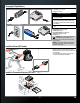
User Manual

7
EN
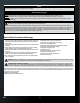
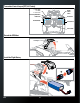
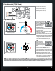
Transmitter Setup (BNF)
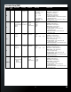
Transmitter Model
Type
Switch Select Reversing Throttle Cut Model Setup Switch Position
DX6i
acro n/a gear - R
All others - N
act
Travel Adj: Flap ↑ 120 ↓ 100
Throttle Subtrim: ↑ 10
Fl aps: FLAP
Norm ↑ 100
land ↓ 100
Mi x 1:
gear → gear act
rate: D –60%, U 0%
SW: ele d/r
Smart Mode = F Mode ( POS. 0)
Return Home = F Mode (POS. 1)
AP MODE = ELE D/R (POS 1)
GI MBAL control = FLAP (POS 1),
Throttle controls gimbal angle
Ac celerometer calibration = Set FLAP to POS 0 and cycle
Flight Mode switch 4 times
Co mpass calibration = Set FLAP to POS 10 and cycle
Flight Mode switch 4 times
DX6
airplane Ch annel Assign:
Channel Input
Con g
(2nd page):
Gear: B
AUX1: A
S ervo setup:
AUX1 - R
All others - N
Th rottle cut:
Position:
–130%
Switch: Switch i
Se rvo setup:
Travel:
120%
140%
AX1
Smart Mode = Switch B ( POS. 0)
AP MODE = Switch B (POS 1)
Return Home = Switch B (POS. 2)
GI MBAL Control = Switch A (POS 1),
Throttle controls gimbal angle
Co mpass calibration = Switch A (POS 1) and
cycle B switch 4 times
Ac celerometer calibration = Switch A (POS 0) and
cycle B switch 4 times
DX7s
airplane Knob: AUX2
Gear: AUX1
Flap: Gear
Se rvo setup:
All NORM
Th rottle cut:
0% Trainer
Se rvo setup:
Travel:
Aux1 120% 140%
Smart Mode = Flap switch ( POS. 0)
AP MODE = FLap switch (POS 1)
Return Home = Flap switch (POS. 2)
GI MBAL Control = Gear switch (POS 0),
Knob controls gimbal angle
Co mpass calibration = Gear switch (POS 0) and
cycle FLAP switch 4 times
Ac celerometer calibration = Gear switch (POS 1) and
cycle FLAP switch 4 times
DX8
airplane Gear: AUX1
Knob: AUX2
F Mode: Gear
Se rvo setup:
All NORM
Th rottle cut:
0% Trainer
Se rvo setup:
Travel:
Aux1 120% 140%
Smart Mode = F Mode switch ( POS. 0)
AP MODE = F Mode switch (POS 1)
Return Home = F Mode switch (POS. 2)
GI MBAL Control = Gear switch (POS 0),
Knob controls gimbal angle
Co mpass calibration = Gear switch (POS 0) and
cycle FLAP switch 4 times
Ac celerometer calibration = Gear switch (POS 1) and
cycle FLAP switch 4 times
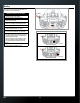
DX9/DX18
airplane Ch annel Assign:
Channel Input
Co n g (2nd page):
Gear: B
AUX1: A
AUX2: R Knob
Se rvo setup:
All NORM
Th rottle cut:
Position:
–130%
Switch: Switch i
Se rvo setup:
Tr avel:
140%
120%
AX1
Smart Mode = Switch B ( POS. 0)
AP MODE = Switch B (POS 1)
Return Home = Switch B (POS. 2)
GI MBAL Control = A switch (POS 0),
Knob controls gimbal angle
Co mpass calibration = A switch (POS 0) and
cycle B switch 4 times
Ac celerometer calibration = Gear switch (POS 1) and
cycle B switch 4 times