In Car Video IVSC-5502 Operating and installation instructions http://www.blaupunkt.
CONTENTS General information ............... 11 Installation and safety notices ........ 11 Accessories .................................. 11 Supplied parts ........................ 12 Switching on/off .................... 12 Switching on the signal controller .. 12 Switching off the signal controller .. 12 Settings .................................. 13 External monitor switch (Fig. 2) ...... 13 Monitor connections ...................... 13 IR remote control ................... 13 Functions .............
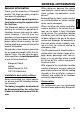
Installation and safety notices Before connecting your signal controller, please read the following information carefully. The battery’s negative terminal must be disconnected for the entire time it takes to install and connect this device. Accessories We recommend you use accessories that have been approved by Blaupunkt. ENGLISH FRANÇAIS ITALIANO NEDERLANDS SVENSKA ESPAÑOL Blaupunkt GmbH Hotline Robert Bosch Str. 200 D-31139 Hildesheim PORTUGUÊS Thank you for choosing a Blaupunkt product.
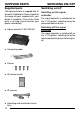
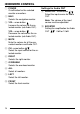
SUPPLIED PARTS SWITCHING ON/OFF Supplied parts Switching on/off The signal controller is supplied with all the parts listed below. Please check that the range of parts supplied with your device is complete. If one of the listed parts is missing, please contact your dealer immediately. Switching on the signal controller ● Signal controller 7 607 003 551 The signal controller is switched on via the “+12V ignition” switching line by the connected control device.
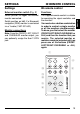
SETTINGS 1 POWER NAVI MUTE 4 < BOOSTER AUDIO CH VOL CH 5 : FRONT 9 LEFT ESPAÑOL ; ALL PORTUGUÊS Note: From the FRONT, LEFT, RIGHT and OVERHEAD monitor output, you can optionally assign the 8 or 13 PIN jack. RIGHT 8 OVERHEAD IVRC 05 7 DANSK Monitor connections ENGLISH The supplied remote control is suitable for operating the signal controller and the monitors. You must enter a button combination in order to control a single monitor or all the monitors simultaneously.
IR REMOTE CONTROL 1 POWER On/off button for the selected monitor or monitors. 2 NAVI Selects the navigation monitor. 3 VOL • arrow button Increase the volume for the selected monitor (not Audio OUT). VOL • arrow button Decrease the volume for the selected monitor (not Audio OUT). 4 MUTE Mute the volume for all the connected monitors and Audio OUT. 5 CH • arrow button / Select the input source for the selected monitor. 6 RIGHT Selects the right monitor. 7 OVERHEAD Selects the overhead monitor.
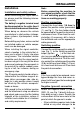
Connect the switching positive cable (2) (see Fig. 1) to the switching positive ) of the main deoutput (ignition vice (e.g. car radio or navigation device). If connecting to terminal 15 of the vehicle, protect the switching positive cable (2) by installing a fuse holder (1A fuse) at a maximum distance of 20 cm from the point of connection. ENGLISH FRANÇAIS ITALIANO Switching positive NEDERLANDS Connect the fuse holder (1A fuse) to protect the positive cable (permanent (1), see Fig. 1).
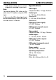
INSTALLATION made to the vehicle, please contact a specialist workshop in your area. Note: You cannot display PAL video on the wide vision TV monitor using the RGB input. In this case, the PAL video signal must be connected directly to the AV input of the wide vision TV monitor.. SPECIFICATIONS Specifications Video input: Composite Video, 1.0 Vpp, 75 ohms Audio input: 0 - 1.0 Vrms, 20 Hz-20 kHz (Booster off) 0 - 0.3 Vrms, 20 Hz-20 kHz (Booster on) RGB input (video signal): 0.
SPECIFICATIONS DEUTSCH Features 5 Audio inputs: Cinch jacks ENGLISH 4 Video inputs: Cinch jacks 1 RGB input: 15 pin Sub-D socket FRANÇAIS 4 monitor outputs: Composite video, audio L/R, control, 13-pin (8-pin) jack, with power, earth and switching positive ITALIANO 1 RGB output: 15-pin Sub-D plug-type connector NEDERLANDS 1 Audio output: Cinch jacks 10dB booster on/off Conversion: RGB to CCVS CCVS to RGB SVENSKA IR remote control IR receiver Power input: 4-pin plug-type connector DANSK PORTUGUÊS
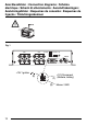
Anschlussbilder • Connection diagrams • Schéma électrique • Schemi di allacciamento • Aansluittekeningen • Anslutningsbilder • Esquemas de conexión • Esquemas de ligação • Tilslutningsskemaer 12V Fig.
DEUTSCH Fig. 2 CH3 Ext-monitor IR DC 12V IN CH5 RGB-IN AUDIO-IN CH4 Audio in-right FRANÇAIS CH2 ENGLISH CH1 IR-Empfänger (Eingang) IR receiver in Video in Audio in-left ITALIANO Externer Monitorschalter FRONT LEFT RIGHT OVERHEAD Audio OUT R SVENSKA RGB OUT NEDERLANDS Fig.
1 out CDC CDC-A08 IDC-A09 RGB-Y-Cable C1-4x Cinch AUX 2-in RGB-Cable 2 3 4 5 RCA-Cable 1 7 607 001 508 7 607 001 601 (1,5) 7 607 001 602 (4m) 7 607 893 093 (0,35m) 7 607 001 600 7 607 885 093 (1,3m) 7 607 886 093 (5m) Anschlusskabel/Additional Cables: Speakers 3 2x Aux-in Preamp CDC AUX 2 in out in 4 1 1 AV in Video 4 Audio L 4 Audio R 4 RGB IN Audio IN Video 3 Audio L 3 Audio R 3 Video 2 Audio L 2 Audio R 2 Video 1 Audio L 1 Audio R 1 Digital out Signal Controller IVSC-5502 A
Service-Nummern / Service numbers / Numéros du service aprèsvente / Numeri del servizio di assistenza / Servicenummers / Telefonnummer för service / Números de servicio / Números de serviço / Servicenumre Country: Phone: Fax: WWW: http://www.blaupunkt.