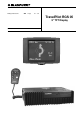
Fitting instructions GB Page 21 - 39 TravelPilot RGS 05 5" TFT Display 8 622 401 120 7 612 001 219
GB Use the enclosed mounts to attach the magnet field sensor to a window which cannot be opened or, especially where estate wagons or liftback cars are concerned, mount it without fasteners underneath the inside roof lining using double-sided sticky tape. Basic unit: 5 A wire fuse 5 A miniature fuse Perfect functioning In order for the navigation unit to function perfectly, it is necessary to calibrate the system after the installation.
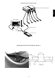
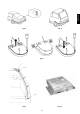
Wheel sensors and magnetic strips Fig. 4 Seen from the driving direction, the antenna is to be mounted on the righthand side in the rear of the vehicle (passenger’s side, in Great Britain, driver’s side). On notchback vehicles, mount the antenna on the lid of the boot using the corner clamps, Fig. 6. Safety instructions Never screw the wheel sensor clamp onto any stress-bearing parts. On estate wagons and liftback cars, set the antenna on the roof with its magnetic foot, Fig. 7.
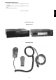
1. Unscrew four screws on the rear side of the display and remove the back plate. 2. Carefully pull off the connector and push through the ball-and-socket base. DEUTSCH Removing the display, fig. 16 DANSK NEDERLANDS Navigation unit FRANÇAIS Componentry Fig. 1 ITALIANO Subject to modifications! ENGLISH 3. Then mount the desired holder.
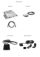
Componentry Fig.
DEUTSCH Componentry Fig.
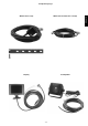
Mounting material Positive-negative connection Fig.
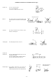
DEUTSCH Precision resistor connection Fig. 3 FRANÇAIS ENGLISH Connection block for the navigation unit ITALIANO Rear window Heckscheibe + Chassis 75 cm measuring wire 50 cm NEDERLANDS rear windo w 250 cm DANSK precision resistor ESPAÑOL SVENSKA Mounting the wheel sensor and magnetic strip Fig. 4 max. 25 mm - 27 - 12.7 mm 12.
Installation tolerances for the wheel sensors Fig. 5 Clearance Z: Z = 6,5 ± 1,5 mm (steel rim) Z = 5 - 0/+ 1 mm (alu rim) referred to the centre of the wheel sensor. Z centre of the sensor Set angle: The edges of the wheel sensor must be set at a distance conforming to Z. Y Y Z ≤ 8 mm The centre of the sensor must be located over the entire circumference of the wheel over the magnetic strip. Z ≥ 5 mm Offset Y: ≤ 10˚ Turning angle: The turning angle must not exceed 10°.
ESPAÑOL loop SVENSKA Fig. 8 Fig. 9 - 29 - DANSK NEDERLANDS ITALIANO Fig. 6 loop Fig. 10 FRANÇAIS Fig.
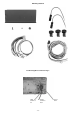
Connecting the sensors for the navigation unit, Fig. 11 Undo the transport block screws and keep them near the unit Navigation head-unit incl. CD-ROM player Display 5" GPS receiver GPS antena 1,3 m Kl. 58d Kl. 15 1,3 m Kl.
or rt br Fig. 13 Fig. 14 - 31 - ESPAÑOL SVENSKA DANSK NEDERLANDS Fig.
5m Fig. 15 Fig.
Service Checklist The following error messages can appear in the top line on the screen in any menu regardless of what function is currently being performed. Check the following points during servicing! 2) Is the basic navigation unit mounted so that it is free of vibration? 3) Has the navigation CD-ROM been loaded correctly into the CDROM player? „Check the compass“: The compass is not connected or the voltage level of the compass is outside of the valid value range.
Error: Frequent loss of locating with message faulty „left“ or „right wheel sensor“ Load the installation disk Select „wheel sensor test“ and drive straight on. Are the impulses for wheel 1 and 2 the same? Is the difference between the counters practically „zero“? yes no Are the magnetic strips damaged? Have the magnetic strips been mounted at the correct distance (5/6.5 mm) to the wheel sensor? Are the magnetic strips in position properly? Run „sensor - emulator test“ for basic navigation unit. O.K.
FRANÇAIS - Load the installation disk. - Select the hardware test „wiring test“. - Switch on the rear window defogger. The indication for „precision resistor“ must change by > 30 points, for example from 435 to 390 Test the basic navigation unit with the „sensor - emulator test“. Test passed? no Replace the basic navigation unit and do a complete calibration. DANSK Check the mechanical wiring to the precision resistor. (Chassis and rear window wiring, signal wire to the basic navigation unit) O.K.
Error: Regular locating loss even after a short drive Load the installation disk. Select „find compass location“, then select „compass ellipse“. Drive the vehicle in a circle. Is there an ellipse visible on the screen inside the squares? yes no Replace the magnetic field sensor. Repeat the „compass ellipse“ test. Is there an ellipse visible on the screen inside the squares? Run the „sensor - emulator test“ on the basic navigation unit. yes no no Install the magnetic field sensor, lay the wiring.
Regular locating loss due to wheel magnetism Demagnetise the wheel and repeat the test. Load the installation disk. Select „find compass location“, then select „compass ellipse“. Drive the vehicle in a circle. Is there an ellipse visible on the screen inside the squares? no Metal parts affect the magnetic field sensor e. g.
Error: Occasional locating loss due to electrical equipment in the vehicle Load the installation disk. Select „find compass location“ and then select „compass error“. Press „reset“. Switch on each piece of electrical equipment individually. The value indicated for „Loc. error“ must be less than „3.5“. Check logical equipment combinations as well. The sum of the values for the equipment must not exceed a „Loc. error“ of 3.5.
No GPS satellite reception for several days DEUTSCH Error: Check the connection wire from the GPS receiver to the navigation and the power supply. yes no Replace defective wiring or fuses. Do not calibrate the basic navigation unit. Replace the GPS receiver. Wait approximately 1 minute. yes no Install the GPS receiver properly. Do not calibrate the basic navigation unit. Replace the basic navigation unit and do a complete calibration.