SA 2700 Kit User Manual
Table of Contents 1. System Installation Planning ____________________________________________ 1 2. Device Introduction ___________________________________________________ 3 3. First Time Setup ______________________________________________________ 6 4. Mount Devices _______________________________________________________ 8 5. System Default Setting ________________________________________________ 11 6. User Menu __________________________________________________________ 12 7.
1. System Installation Planning Home and Away Arm Mode Planning The alarm system supports two arming modes: Away Arm and Home Arm. Away Arm mode will arm all accessory devices installed in the system to raise alarm when activated; Home Arm mode will partial arm the system so that no intruder could get inside the premises without triggering an alarm, yet the user can move within the house freely.
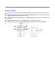
Device Location Panning: Door Contact The Door Contact should be mounted as high as possible. Do not aim a PIR sensor at this door/window. Remote Controller It is used inside or outside your home and can be kept on the key ring PIR Sensor Mount the PIR sensor at 6.2-6.6 ft. height for best performance. When mounted at 6.6 ft. height, the PIR sensor has a range of 39 feet (13 yards).
2. Device Introduction The Alarm System supports multiple devices which are listed in this section. For accessory devices, please refer to individual device manual for detail instruction. NOTE: The kit package you purchased includes the following devices: 1 x PIR Sensor, 1 x Door Contact, 1 Remote Controller For other useful devices, see http://www.blaupunkt.
PIR Sensor The PIR sensor detects movement and raise alarm when it detects an intruder. The PIR sensor is powered by 2 1.5V AA alkaline batteries pre-inserted by factory. Pull out the plastic battery saver tab on the back of PIR sensor, this will activate the batteries. The LED will flash for 30 seconds to indicated the PIR is warming up When the battery voltage runs low, please follow instruction below to change batteries: 1. Remove the screw at bottom of PIR sensor to open the cover. 2.
Remote Controller You can arm, home, disarm, and activate an Emergency alarm with your Remote Controller For disarming action, you can only use Remote Controller to disarm the system after you have triggered an entry Door Contact or PIR sensor. The Remote Controller is powered by a CR2032 3V lithium coin cell which is included in the package. Open the back battery cover to insert the battery, then replace the cover.
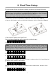
3. First Time Setup This quick guide will take you through a step by step process of system initial setup. NOTE: The First Time Setup process is only availble when you power on the Control Panel for the first time. Once the process is completed, it will not appear again. All of the options can be changed later again, do not worry if you make any mistakes. Detail system setting can be done later by accessing the Programming Mode. 1. Remove the screw on the GSM Module compartment cover, lift the cover.
Press OK to continue, enter a 4-digit PIN code. Press OK to confirm. 5. E x i t S e t u p R e p e a t S e t u p If you are satisfied with current setting, select Exit Setup and press OK to confirm. If you want to make changes to current setting, select Repeat Setup and press OK to confirm. You will be returned to the beginning of the First Time Setup process . NOTE: If no devices are included in the Control,Panel. When you choose Exit Setup, the LCD will display: Please add at least 1 device.
4. Mount Devices This chapter will guide you through device mounting process. After you complete First Time Setup process, if the Control Panel has already included accessory devices, the screen should display: M o u n t s e e D e v i c e s ma n u a l Proceed to mount your sensors and accessory devices, tamper alarm will be disabled while the Control Panel remains under this screen for you to install devices without triggering tamper alarm.
3. Hook the Control Panel onto the plate, then slide the control panel left to secure the panel and depress the tamper switch against the mounting plate. (Figures 4) Figures 4 PIR Sensor The PIR Sensor has knockouts on the back where plastic is thinner. The 2 central knockouts are for flat wall mounting, and the four side knockouts are for corner mounting. (Figure 1) 1. Break through the knockouts, use the knockouts to mark position on wall or corner.
Door Contact The Door Contact has two knockouts on the inside of the back cover where plastic is thinner for wall mounting. (Figure 1) The Door Contact should be mounted on the door/window frame, while the magnet should be mounted on the door/window. 1. Break through the knockouts; mark the mounting location on door/window frame using the knockout as template. (Figure 2) 2. Drill holes into the wall, insert wall plugs if required. (Figure 3) Figure 1 Figure 2 Figure 3 3.
5. System Default Setting Entry/Exit Time and Device Attribute When the system is armed and an Entry device is triggered, the Entry timer will begin to count down (default 20 seconds). The system must be disarmed before the timer expires, or a Burglar alarm will be activated. When the system is being armed, the Exit timer will begin to count down (default 30 seconds), the system will ignore any sensors triggered during this period.
6. User Menu The User Menu displays the system basic information and allows you to test system function Entering User Menu When the system is in Disarmed Mode (Alarm off), enter your User PIN Code to access User Menu. Press a numeric key or En t e r key, the display will prompt you to enter the PIN code: Co d e . . . Enter the complete PIN code and press OK within 30 seconds to enter User Menu.
Walk Test Walk Test allows you to test the signal range of sensor and accessory devices. To test the device 1. Press the test or learn button on the device, refer to device user manual for detail. 2. If the Control Panel receives the signal, the screen will display device type, zone number, attribute, name signal strength in 0~9 scale accordingly. (Signal strength 9 being the strongest) GSM Signal Use GSM Signal function to check the Control Panel GSM signal strength at current location.
7. Programming Mode To access the Programming Mode, you need to first enter the User Menu, and select P-Mode under User Menu. The screen will prompt you to enter the Master Code. P - Mo d e E n t e r M- C o d e . . . . Enter the Master Code within 30 seconds and press OK to enter Programming Mode. The system default Master Code is 1111. The Programming Mode items include: Walk Test – Device range test Tel. Setting – Telephone number setting Gen. Setting – General setting Spc.
4. Select the report type for this telephone number, there are 2 choices: Voice Report – The Control Panel will dial the telephone number and play pre-recorded voice message according to the event upon answer. Telephone number set to Voice Report will be marked with “V” in the telephone number menu. SMS Report – The Control Panel will send a SMS message to the telephone number to notify the user.
General Setting Program your system general setting under this menu. The items available include the following – see a) to g): a) PIN Code The PIN code is used to access the User Menu, and Arm/Home/Disarm the system. The system can store up to 4 User PIN Codes, each PIN code consists of 4 digits. When you Arm/Home/Disarm the system, the Control Panel will record the User PIN Code used to perform the action in system log for you to review.
e) Door Chime This function allows you to decide whether the Control Panel should emit a two-tone Door Chime sound to notify the user when a Door Contact or PIR Detector set to Entry is triggered under Disarmed mode. Options available are : High, Low, Off Door Chime Off is set as factory default. f) Time This is for you to program the current time to be displayed. (Hour & minute) Use Up and Down keys to select the Hour and Minute, and press OK to confirm.
logged, reported to programmed telephone number and displayed on the LCD to warn the user. Detection Off is set as factory default. e) Final Door If set to On, when the system is being Away Armed and a Door Contact set to Entry attribute is closed before the Exit Delay timer expires, the system will enter Away Arm mode immediately even if the Exit Delay timer has not expired yet. If set to Off, the system will only enter Away Arm mode after the Exit Delay Timer has expired.
Device +/Devices +/- allows you to add/remove /edit devices. The functions include: Add Devices Edit Devices Remove Devices Learn PSS Add Devices 1. To learn in a device, select Add Device, press “OK” to confirm. 2. Press the test /learn button on the device, refer to device manual for detail. 3. If a signal is detected, the screen will display the device information, press “OK” to confirm. If the device already exists in system, the screen will display “Already exist in system”: 4.
Remote Controller --- RC Remote Keypad ---KP Smoke Detector --- SD Temperature Sensor --- TS Outdoor Siren --- BX Edit Devices Use Edit Device to change setting for learned in devices. The screen will display available devices. 1. Select the device you want to edit, press “OK” to confirm. 2. Edit the device information according to the setting in Add Device. Remove Devices This function is used to remove an existing device from the system. 1.
Reset GSM Reset GSM function allows you to reset your GSM module. You can reset the GSM if the Panel has GSM related fault conditions to try to solve the problem. 1. When you select the function, the screen will display “Please wait”. Do not touch the Control Panel during the GSM reset process 2.
8. Operation This chapter covers system general characteristic under normal operation. Away Arm Away Arm will arm all devices in the system Arming the System When the system is under Disarm mode: 1. Press the “Arm” key on the Control Panel, Remote Controller, or Remote Keypad. 2. The Exit Timer will be displayed and begin to count down according to system setting. 3. When the Exit Time is up, the Control Panel will sound a long beep.
Force Arm When you arm the system, if any fault event exists, the Control Panel will sound a ding-dong warning sound to indicate arming is prohibited, the fault event will be displayed on screen. At this moment, you can first rectify all of the problems and then clear the Fault Display and you will be able to arm the system normally. If you want to Away/Home Arm the system without solving the fault event. Follow steps below to Forced Arm. 1.
Stopping the Alarm Enter a User PIN Code and press OK key on the Control Panel. Enter a User PIN Code and press Disarm key on the Remote Keypad. Press Disarm key on the Remote Controller The alarm will be stopped; the device that triggered the alarm will be displayed on screen. Use the Down button to scroll down the alarm event, the screen will display whether the system reported successfully to programmed telephone number or not.
If more than one number is programmed the Control Panel will continue to dial the number(s) until a recipient presses the third response key. If no phone number is programmed, the Control Panel will not dial. Call Acknowledgement When the Control Panel makes Voice Report, there are 3 responses available for the recipient to receive the call, by pressing 1, 0 or 9 key on his telephone set.
9. Connect2Home Application What is “Connect2Home” application? The Connect2Home application is a free smart phone application designed to help you remotely operate and program your alarm system by sending SMS commands. It has a clean and intuitive interface for easy recognition and operation. Furthermore, the Connect2Home application features extra Home Automation setting which allows you to control your home appliances automatically if you have included Power Switches in your alarm system.
10. Troubleshooting & Factory Reset This chapter covers the potential issues you may encounter during system operation, and factory reset function Control Panel Control Panel Fault Orange LED indicates fault in system, When the LED light up, please enter User Menu and select Fault Dsp to view fault events. The possible fault events include: Control Panel / Devices low battery: -- Change device batteries or charge Control Panel battery accordingly.
PIR is slow to respond: -- This is normal. PIR has sophisticated false arm filter setting to prevent accidental trigger. It is also less sensitive when walking directly toward it: PIR give false alarm: -- Make sure pets have no access to protected area. -- Make sure the PIR is not pointed at source of heat or moving objects Door Contact Door Contact LED flashes when activated: -- Door Contact is on low battery or tamper switch triggered.
11. Specifications All Devices Environmental Condition -10°C to 40°C, relative humidity 85% non-condensing for Control Panel and all devices. Radio Operation Range About 30m in typical domestic installation, range can vary depending on building construction, device location, and environment. Control Panel Display 2x16 character LCD Keypad 17 keys keypad Siren Output 96 dBA sound pressure @ 1m minimum Zones 30 radio devices (Plus 4 optional Power Switches). Power Supply DC9V 1A Power Adaptor Battery 4.
Compliance Statement Declaration of Conformity This device complies with the requirements of the R&TTE Directive 1999/5/EC and the following harmonized standards have been applied: Health: EN50385:2002 Safety: EN60950-1:2006+A11:2009+A1:2010+A12:2011 EMC: EN 301 489-1 V1.9.2:2011-09, EN 301 489-3 V1.4.1:2002-08 EN 301 489-7 V1.3.1:2005-11 Radio: 3GPP TS 51.0 10-1 V9.8.0, EN 301 511 V9.0.2 (GSM 13.11) 3GPP TS 51.0 10-1 V9.8.0, 3GPP TS 51.010-2 V9.0.1 3GPP TS 51.010-4 V4.14.1, 3GPP TS 51.010-5 V9.0.