
Operating Instructions and Installation Instructions

74
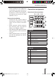
Chamber C1
(Equaliser/Amplifi er)
1 Line out LR
2 Line out RR
3 Line out GND
4 Line out LF
5 Line out RF
6 +12 V switched*
Chamber C2
(car phone/optional IR remote control
RC 10)
7 Telephone IN+
8 Telephone IN-
9 Telephone mute (active low)
10 +12 V switched*
11 Remote control IN
12 Remote control GND
Chamber C3
13 CDC data IN
14 CDC data OUT
15 +12 V continuous positive
16 +12 V switched*
17 CDC data GND
18 CDC AF GND
19 CDC AF L
20 CDC AF R
* Sum. total 400 mA
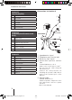
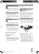
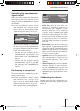
Connections in chamber A
1 Speedometer signal
2 Telephone mute (active low)
3 Reversing light signal
4 Continuous positive connec-
tion
Terminal 30 battery +12 V.
Cable cross section min. 1.5 mm
2
.
Do not route the cable alongside
wire harnesses!
Connect the safety bracket for
shielding the positive cable and at-
tach it to the positive pole of the
battery!
5 Control cable
(Power Antenna +)
Switched positive output for exter-
nal components, such as a power
antenna.
Max. load <150 mA
Relais
12V
12
V
A
8 604 390 045
KL. 15 +12 V
5
7
8
6
4
3
2
1
Installation instructions
ROMENAV55Eman_star_ois_eng.indd 74ROMENAV55Eman_star_ois_eng.indd 74 06.12.2005 16:04:47 Uhr06.12.2005 16:04:47 Uhr