Q-SERIES MANUAL
User’s Manual for the Blender Q-Series Table of Contents Cautions for Safe Usage. . . . . . . . . . . . . . . . . . . . . . . . . . . . . . . . . 4 Product Specifications. . . . . . . . . . . . . . . . . . . . . . . . . . . . . . . . . . 4 Components & Names. . . . . . . . . . . . . . . . . . . . . . . . . . . . . . . . . . 5 Installation & Cautions . . . . . . . . . . . . . . . . . . . . .
1. CAUTIONS FOR SAFE USAGE 1-1. SAFETY CERTIFICATION All the components of the blender have been certified according to such standards as ETL (which satisfies the UL Standard 763.), CE and NSF International R 1-2. CAUTIONS FOR OPERATION • . Be careful not to put any part of your body, clothes or household appliance into the running socket or come into contact with blades while the blender is in operation. • Do not put anything into the blender with your hand while the blender is in operation.
3. COMPONENTS & NAMES 3-1. CHECK WHETHER THE FOLLOWING COMPONENTS ARE PRESENT. COMPONENT (unit) QUANTITY Main Body (Blender Q – Series) 1 Blender Jar (JAR-2) 1 Blender Jar Cover 1 User’s Manual 1 User’s Manual for the Program 1 Additional Blender Jars (JAR-2) Separately Sold 3-2.
1 - Built-in Noise-Absorbing Case 5 - Noise-Preventing Case Cover 2 - Lower Case 6 - Lower Case Cover 3 - Noise-Preventing Case 7 - Motor 4 - Jar • The Blender Q-Series products can be easily assembled or dismantled by anyone. (You can assemble or dismantle the products without using any special tool.) • Visit our Internet homepage (http://aspenkorea.com) in regard to the user’s manual for assembling or dismantling the products. www.aspnekorea.com 4. INSTALLATION & CAUTIONS 4-1.
Cautions: The blender absorbs the surrounding air through the vent under the motor. Then, the hot air is discharged through the vent on the upper side of the motor. A sufficient amount of air must be circulated through the lower part of the motor. and cooled down. You must circulate the hot air and cool it down. You must not put such light items as vinyl bags and paper cups around the motor of the blender. (Such items can be absorbed in the motor for the circulation of the air.) 5. USAGE 5-1.
usage. • The Blue LCD screen indicates the number of the cycle, the remaining time and the speed while the blender is in operation. 5-3. OPERATING METHOD AND INSTRUCTION ON THE PROFILE FOR Q-SERIES APPLICATIONS Adjustment Method for the Program Multi 3-P-3 Smoothie 3-P-2 Coffee 3-P-1 If you push each profile code according to the order shown in the above table, you will hear the buzzer sound of ‘Beep’ and see the changed indication of the program configuration on the blue LCD screen.
CLEANING OF THE JAR • Put 1L of hot water and .25ml of detergent (kitchen detergent etc.) in the jar. • Close the lid of the jar tightly. Put the jar on the motor and push the P-button (Pulse-button) for about 15 seconds. • Clean the detergent on the jar and the cover with clean water. • Do not use the dish sponge when cleaning the detergent. Use a soft piece of dishcloth or ordinary cloth to wipe out the detergent.
become blunt, but there is no problem with the mixing power. (The blade is not sharp.) • RUNNING SOCKET: The running socket (Refer to Figure 1.2) is subject to the warranty during the lifecycle of the product. • The warranty is applied from the delivery date or the purchasing date when the purchasing certificate is submitted. (The apparent defect or the damage caused by misuse is not subject to the warranty.) 7-2.
PROCESS IS EXECUTED. DOES THIS MEAN THAT THERE IS A PROBLEM WITH THE MOTOR? • Such a situation is caused by the incomplete blending process due to the hollowing phenomenon. • When the blending process is executed, all the small pieces of ice generated at the initial stage become instantly cooled down and prevented from being mixed. As a result, the ice is not ground.
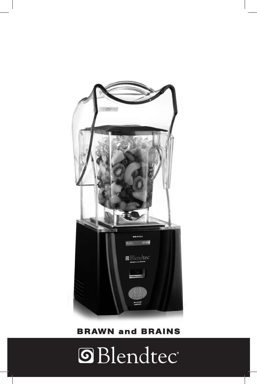
APPENDIX - PRODUCT DIAGRAMS FIGURE 1.1 - FRONT VIEW: BLENDER MOTOR AND JAR Lid Jar Blade Assembly LCD Screen Power Switch FIGURE 1.
9.35” (237.49 mm) SIDE VIEW (OPEN ENCLOSURE) 9.35” (237.49 mm) SIDE VIEW FRONT VIEW 18.41” (467.62 mm) 9.29” (235.96 mm) 18,41” (467.62 mm) 22.51” (571.75 mm) FIGURE 2.1 - ABOVE COUNTERTOP (65.78 mm) 2.
8.97” (227.8 mm) SIDE VIEW 8.49” (215.6 mm) FRONT VIEW 10.24” (260 mm) 10.24” (260 mm) 3.03” (77 mm) SIDE VIEW (OPEN ENCLOSURE) 8.00” (203.2 mm) 14.37” (365 mm) FIGURE 3.
FIGURE 4.1 - COUNTERTOP HOLE TEMPLATE 5-7/8” (149.22 mm) 4-3/8” (111.
1206 South 1680 West Orem, UT 84058 801-222-0888 www. blendtec.