I NSTALLA T I ON MANUAL VOL.1 “BLITZ”-the abiility to innovate the motor vehicle boundaries.
- Index - ● Index 01 ● Parts List 02 ● Safety Notice 03-04 ● Important Notice 05-06 ● Installation Method ● MODE Explanation ● MODE Diagram 10 ● Switch Operation 11-12 ● Initial Setting 13-15 ● Trouble Shooting ● MEMO 07 08-09 16 17-19 1
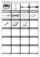
- Parts List - ※ 137 X 98 X 28 mm ※ Length of harness:150 cm Main Unit ※ Length of Harness: 30 cm 1 ※ Length of Harness: 150 cm Remote Controller 1 Main Harness ※ Length of Harness: 14 cm 1 Sensor Harness 1 1 Double Sided Tape 1 ※ Length of Harness: 150 cm Cigarette Plug 1 RCA Cable 1 Zip Tie 1 Installation Manual 1 2 Battery (CR2025) Application List 1 1
- Safety Notice - ■ In order to use the product safely, please read the “SAFETY NOTICE” thoroughly. *Notes on“How to use this product”and“Installation procedures”are explained in detail in this manual. Please read it thoroughly and use it correctly. *Blitz Co. Ltd will not be responsible of any breakage and manfunctions caused in installing this product with a vehicle with a third party’s product(s) and (or) with a reconstructd vehicle. *Blitz Co.
- Safety Notice - CAUTION A potential possibility of a serious injury and (or) even death can be assumed to the individual and (or) to the third party if this indication is ignored and wrongful usage and (or) operation is performed. (This product is designed to work on a 12V DC and the ground is designed to be the chassis of the vehicle) It would causea fire by installing this product on other than a vehicle powered by a a 12V DC.
- Important Notice - In order to operate this product properly and safely, please read this intallation manual/application chart and also vehicle’s monitor operation instruction, before installation/operation. Also, for this products and other oprtional equipments, please read each individual instruction manuals.
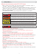
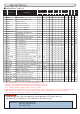
- Important Notice- ■Display/Control Item List Unit No Item Title Item Content SI Meter 3 fold 6 fold Graph USA Main Sub Main Sub Main FUEL A/F Control Rec Play WARN 01 SPEED Vehicle Speed MPH rpm ○ ○ ○ ○ ○ ○ ○ ○ ○ ○ - - ○ ○ - - ○ Engine Speed km/h rpm ○ 02 TACHO ○ ○ 03 WATER TEMP Engine Coolant Water Temp ℃ ° F ○ ○ ○ ○ ○ ○ - - ○ ○ 04 IGNIT Ignition Timing deg deg ○ ○ ○ ○ ○ ○ ○ Injector Open Time ms,% V,% ○ ○ ○ ○ ○ ○ - - ○ 05 INJCT - -
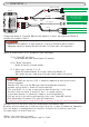
- Installation - Harness for the sensors 3P To A/F BOX (Sold separately) or Press Sensor (Sold separately) Main Unit 2P Main Harness (A) To Temp Sensor (Sold separately) To vehicle diagnostic connector (Refer to the application list for the connector location) (B) Cigar lighter plug To cigar lighter socket (Depending on the installation method) RCA cable To Video input connector (C) To audio input connector (Left) To audio input connector (Right) ①Connect the harness as illustrated.
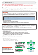
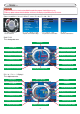
-Modes - Important NOTE ①Pictured used in this manual may be editted for explanation purpose.Actual display may vary. ②Blitz may update software without notification. In that case, the display may be different from this manual. ①MAIN MENU/CALIBRATION/FUNCTION/EXT (1)MAIN MENU Goes to main menu (3)FUNCTION Set parameters for each function (2)CALIBRATION Adjust the communication settings (4)EXT Connect to external devices ②METER This isAnalog meter menu.
- Modes - ④Digital Meter (6 fold) This is digital meter menu. 6 items are displayed. Current Value Peak Value First Display Fourth Display Second Display Fifth Display Third Display Sixth Display Warning Mark Peak Renewal Mark Rec Indicator Records current displayed items only Replay Indicator Does not display peak value during replay Notes (REC function) ・Records up to 10 minutes (depends on number of displays). Sampling rate is 1 sample/0.2sec.
Back Enter Down Back x2 Down Back x2 Enter Enter Down Enter Enter Back Enter Down 10 Back Down Enter Back Enter Down - Mode Diagram - Down Down Down
Operation DOWN RIGHT LEFT Main Menu Mode select Mode select Mode select Mode select Meter Shortcut to A/F graph Shortcut to 3 meters display First Display Change Mode First Display Change Mode Meter Type Change reverse Meter Type Change Second Display Change Mode Meter Display Second Display Change Mode Meter Type Change reverse Meter Type Change Third Display Change Mode Meter Display Third Display Change Mode Meter Type Change reverse Meter Type Change To Meter Display Meter Dis
Operation Calibration Function UP DOWN Select Item Select Item RIGHT LEFT Decide Selection EXT Graph Fuel Injection Trace To MAP Mode Select Item Shortcut to 6-fold meter A/F Adjustment Mode Increase value Digital Display selection Select Display Item Graph A/F Graph Change Record Memory 12 Change Memory source Demo Mode ENTER Select Item Select Item BACK Decide Selection To Main Menu To Graph Menu To Change Digital Display Select Higher rpm Range Select Lower rpm Range Decide r
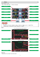
- Initial Setup- Note This section explains about initial setup. If only minimum function of R-Vit DS is required, please follow instruction number ①,②,③,⑤,⑥,⑨ ①Initialize Select Reset frum FUNCTION menu to initialize the unit. Note There are also “All Peak Clear” and “All Graph Memory Clear” to clear the value. ②Select vehicle type Select Vehicle type (refer to application list) from “Car Type” in the CALIBRATION menu.
- Initial Setup - ⑪Fuel Pressure setting: Only applicable to vehicle specified on the application list. (1)Select Fuel Pressure from FUNCTION menu. (2)Select CONTROL, then select ON to control fuel pressure, OFF to use normal setting. (3)Select REVO to set the trigger RPM to startthe fuel pressure control. (4)Select Press[%] to decrease/increase the fuel pressure from -9.9% to +25%. Change beyond engine capability can damage the engine. Always ask professional to setup the active control.
- Initial Setup - ⑭Warning Setup (1)Select “Warning” from FUNCTION menu. (2)Select “Source” to set up the warning item. (3)Select “Warning Switch” to switch on/off the warning function. (4)Select “Sound” to select the alert sound for the warning. (5)Select “Watch Direction” to set which direction (Over/Under) to watch. (6)Select “Set” to set the warning value. Maximum of two warning items can be set. Note (1) (2) (3) (4) ⑮Voltage Input Setup (1)Select Voltage Input Setup from FUNCTIOON menu.
- Troubleshooting - When the product does not work properly, please trouleshoot following the chart below.
- MEMO - 17
- MEMO - 18
- MEMO - 19
“BLITZ”-the abiility to innovate the motor vehicle boundaries.