
Manual


(1)
(4)
(3)(2)
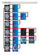
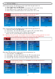
⑭Warning Setup
(1)Select “Warning” from FUNCTION menu.
(2)Select “Source” to set up the warning item.
(3)Select “Warning Switch” to switch on/off the warning function.
(4)Select “Sound” to select the alert sound for the warning.
(5)Select “Watch Direction” to set which direction (Over/Under) to watch.
(6)Select “Set” to set the warning value.
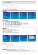
⑮Voltage Input Setup
(1)Select Voltage Input Setup from FUNCTIOON menu.
(2)Select “Low” and input minimum input voltage value.
(3)Select “Fit (Low)” and input minimum Fit(Displayed) value at minimum voltage.
(4)Select “High” and input maximum input voltage value.
(5)Select “Fit (High)” and input maximum Fit(Displayed) value at maximum voltage.
(6)Select “Index” and input the title of input voltage name.
(7)Select “Unit” and input the unit of Fit value.
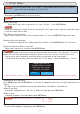
⑯ Unit setup
(1)Select Unit from FUNCTION menu.
(2)Select the desired unit from the list.
(3)Select “Injection” and select the unit for the injector open time.
(4)Select “Air Flow” and select the unit for the Air Flow Sensor.
(5)Select “Throttle” and select the unit for the Throttle opening angle.
Example 1: In case of pressure sensor
Low: 0.5, Fit(Low): 0.0, High: 4.5, Fit(High): 10.0
Example 2: In case of A/F BOX
Low: 0.0, Fit(Low): 10.0, High: 5.0, Fit(High): 20.0
Note
(1)
(6)
(3)
(2)
Note
Note
Maximum of two warning items can be set.
When value other than 0 is set from (3) to (5), it displays % value.
Please set corresponding value for each input. (i.e. XX ms is 100 % for the injector)
For vehicles which provide the information in % basis from the biginning, (3) to (5) will not be displayed.
- Initial Setup -
15