Version: 1466002 2008/6
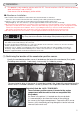
-Safety Notice - In order to use the product safely, please read the “SAFETY NOTICE” thoroughly. Explanation of displayed terms. DANGER Ignoring these indications may cause serious injuries or even death to the individual and (or) to a third party. CAUTION Ignoring these indications may cause serious injuries or injuries to the individual and (or) to a third party. ATTENTION Ignoring these indications may cause injuries or minor injuries to the individual and (or) to a third party.
ATTENTION Ignoring these indications may cause injuries or minor injuries to the individual and (or) to a third party. It may also cause malfunctions and breakages to the product and (or) to the vehicle. ・About the LCD screen. The LCD screen may seem dark or distorted if seen through polarized sunglasses. ・Ask for a professional or a technician to perform the installation of this product. The individual performing this installation must have technical skills and knowledge to perform this installation.
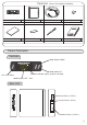
(Please check before installation) PO WE R Parts List Controller 1 Main Unit 1 Double Sided Tape (L) 1 Double Sided Tape (S) 1 Sensor Harness Tie Wrap 1 Splice 1 4 Installation Manual 1 - Product Description Controller PO WE R Mode Switch DOWN Mode Switch UP ON / OFF Switch Activation indicator (Lights up when activated) Mode Display: OFF ~ SP3 - Main Unit - Sensor Harness (4 Pins) Sensor Harness (2 Pins) Controller Harness (10 Pins) 4
- Installation ※ This product is only made for vehicles with 12V DC. Do not install on a 24V DC vehicles or on any other vehicle that is not a 12V DC. It can cause a fire or damage(s) to the vehicle. ■ Attention on Installation ※The location of the installation is related where the electronic throttle is controlled. Please be extra careful on the direction and contacting surface while perform the installation.
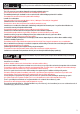
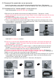
(2) Disconnect the accelerator sensor connector. Usually, the connector is very hard when disconnecting for the first time. To disconnect, use a hair dryer to warm and soften it. Do not use hard tool since it will damage the connector. (3) Installation of the “vehicle specific” sensor harnesss. Install the connectors, besides the BA1 type, as follows. ※Be careful on the direction of the face on the rubber connectors.
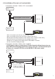
(4) Installation of the main unit and controller 【Connection schematic 1: When +12V is not needed】 To the accelerator Sensor Vehicle specific sensor Harness Main Unit To the vehicles’ Harness PO WE R Controller ・Make sure to plug the 2 pin and 4 pin connectors all the way in. ・Make sure to plug the 10 pin connector from the controller all the way in. ・Bundle together the wiring and attach the main unit where it does not interfere while driving.
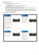
(5) Operational check Perform operational check after installation. ① Turn the ignition key to ON →It will display <OFF> together with a beep after a demonstration screen. →On some vehicles, it will activate by just inserting the key. ② Press the POWER button once. It will display one of the followings. <ECO><SP1><SP2><SP3> ③ Select the desired mode by pressing the UP or DOWN button. ④ There is a safety function that it will always reset itself to <OFF> every time the ignition is turned OFF.
(7) Please read again before driving ※ On AT vehicles and at high speed, the shifting point may feel different since the throttle is opened even if the accelerator is not stepped. There fore, this is not a malfunction. ※ The boost characteristic may change on vehicles equipped with force induction system such as turbo chargers. There is a high possibility that the boost has to be readjusted on vehicles that have been boosted up or the turbo has been changed.