
Manual


Page 8
ROCKLITE RGBW / RGBA Manual Rev. B Copyright (c) 2011 Blizzard Lighting, LLC
Cable Connectors
Cables must have a male XLR connector on one end and a female XLR
connector on the other end. (Duh!)
CAUTION: Do not allow contact between the common and the fi x-
ture’s chassis ground. Grounding the common can cause a ground
loop, and your fi xture may perform erratically. Test cables with an
ohm meter to verify correct polarity and to make sure the pins are not
grounded or shorted to the shield or each other.
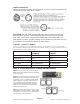
3-Pin??? 5-Pin??? Huh?!?
If you use a controller with a 5 pin DMX output connector, you will need to use a 5 pin to 3 pin adapter.
They are widely available over the internet and from specialty retailers If you’d like to build your own, the
chart below details a proper cable conversion:
Conductor 3-Pin Female
(Output)
5-Pin Male
(Input)
Ground/Shield Pin 1 Pin 1
DMX Data (-) Pin 2 Pin 2
DMX Data (+) Pin 3 Pin 3
Not Used. No Connection. No Connection.
Not Used. No Connection. No Connection.
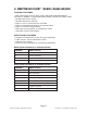
Take It To The Next Level: Setting Up DMX Control
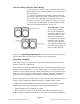
Step 1: Connect the male connector of the
DMX cable to the female connector (output)
on the controller.
Step 2: Connect the female connector of the
DMX cable to the fi rst fi xture’s male connec-
tor (input). Note: It doesn’t matter which
fi xture address is the fi rst one connected.
We recommend connecting the fi xtures in
terms of their proximity to the controller,
rather than connecting the lowest fi xture
number fi rst, and so on.
Step 3: Connect other fi xtures in the chain
from output to input as above. Place a DMX
terminator on the output of the fi nal fi xture
to ensure best communication.