
Automobile Accessories User Manual

Moldboard Assembly 05
Moldboard Assembly
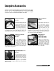
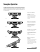
1. Begin the moldboard assembly by first removing each dust cap from
both of the SLIDE BOX CYLINDERS located at the center/rear of the
MOLDBOARD. Attach one 7/16"-20 x 9/16"-18 MALE O.R.B. CON-
NECTOR to each of the retract ports (#7 & #10) and one 9/16"-18 x
9/16"-18 MALE O.R.B. CONNECTOR to each of the extend ports (#8
& #9). Review the diagram below. Note: All of the hydraulic adapters
can be found packaged with the manifold assembly. Reference the
table on page 13 for proper torque specifications.
2. Connect the hoses to each of the hydraulic adapters on the cylinders.
Ports #7 & #10 receive a 1/4" x 36" HYDRAULIC HOSE (P/N 60019).
Note: Review the label on each hose for the appropriate part number.
Ports #8 & #9 receive a 3/8" x 36" HYDRAULIC HOSE (P/N 60224).
3. Next, position the PIVOT BEAM and the A-FRAME, near the mount
locations at the rear of the blade, between the two center support ribs.
Place the right and left group of hydraulic hoses (connected to the slide
box cylinders) through the 1-1/2" diameter rubber grommet openings
in the front face of the pivot beam.
4. Position the pivot beam between the two support ribs until the con-
necting points on the beam align with those on the plow. Insert one
3/4" DIA. x 3" CLEVIS PIN through each mounting hole and secure
them with one 1/4" DIA. x 1-1/2" COTTER PIN.
5. Hook each EXTENSION SPRING to the receiving holes located on
the pivot beam and connect the opposite end of the spring to their
respective SPADE BOLTS. Install the 5/8"-11 x 6-3/8" spade bolts
through the EXTENSION SPRING MOUNTING ANGLE on the top rear
of the blade. Secure each spade bolt by placing one 5/8" flat washer
on the bolt and thread one 5/8"-11 nylon insert lock nut. Tighten each
lock nut until a piece of paper can pass between the 3th & 4th coils
on the spring.
6. Install the flexible BLADE GUIDES at each end of the moldboard.
Insert the 5/16"-18 x 1" hex head cap screw through the holes at the
top of the wing reinforcement rib. Tighten all screws using the nylon
insert lock nuts provided.
Congratulations! You have successfully completed the first stage of
assembly for the Blizzard Power Plow Model 810SS. In the next section
you will assemble the A-frame and the components that are attached to it.
Rod
#7
Base
#8
#9
Base
#10
Rod
DRIVER’S SIDE PASSENGER’S SIDE
Male O.R.B. Connector Adapter
(Ports #7 & #10)
Male O.R.B. Connector Adapter
(Ports #8 & #9)
7/16" 9/16" 9/16" 9/16"
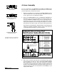
Printed
Label
All of the hoses shipped with the snowplow con-
tain a printed label (with a part number) applied
to the hose. Install the following hoses to their
respective ports on the manifold:
Hose P/N 60091 Ports #1 & #2
Hose P/N 60019 Ports #7 & #10
Hose P/N 60224 Ports #8 & #9
Note: See diagram on page 6.