
Automobile Accessories User Manual
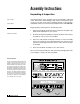

Electrical Assembly - Control Wire Harness 07
Be careful not to overtighten the hose connections. Complete the
hose installation by running each hose through the access holes in
the A-frame to their respective manifold ports.
4. The PRESSURE & TANK HYDRAULIC HOSES attach to the ports on
the side of the manifold labeled “P” and “T”. Verify that the 3/4" x 78"
hydraulic hose with the 1-1/16"-12 female swivel is attached to the
1-1/16"-12 x 1-1/16"-12 MALE O.R.B. CONNECTOR ADAPTER
located in the pressure port (“P”). The 3/4" x 78" hydraulic hose, with
the male O.R.B. 90˚ swivel, connects to the tank port (“T”). Once you
have completed the installation of the hydraulic hoses, begin to install
the wire harness.
When handling the hydraulic manifold DO NOT
hold the manifold by the wire lead coils. The sole-
noid cartridges can bend, causing them to stick
when activated. Always carry the manifold by the
sides of the aluminum block.
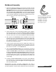
Electrical Assembly - Control Wire Harness
1. Begin the installation by connecting the MALE ELECTRIC CONNEC-
TOR found on the COIL WIRE HARNESS (on manifold) to the FEMALE
ELECTRIC CONNECTOR on the WIRE HARNESS EXTENSION
(PLOW). Once both connectors are locked together, feed the opposite
end of the wire harness extension through the top access hole (same
as 3/4" tank hydraulic hose) in the A-frame located on the driver’s side.
2. Locate the GROUND END RING TERMINAL on the coil wire harness
and wire harness extension. Using a 3/8"-16 x 1-1/2" hex cap screw
and 3/8" tooth lock washer, ground both wires to the A-frame. Secure
the wires using a 3/8" top lock nut. Review the diagram below for the
proper ground location.
3. Next, connect the MOLDED RUBBER CONNECTOR from the wire
harness extension (plow) to the connector on the WIRE HARNESS
EXTENSION (VEHICLE). Lock together the remaining male electric
connector on the PISTOL GRIP CONTROL HARNESS to the female
electric connector on the wire harness extension (vehicle). Complete
the electrical assembly by attaching the BLACK, GROUND wire from
the wire harness extension to the cab of the skid steer. The PINK/
BLACK POWER wire connects to a switched (on and off with ignition)
power source with a minimum of 12 volts.
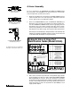
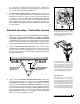
Manifold Mount Holes
There are three sets of holes in the bottom plate
on the A-frame. Each set is used for specific
model year snowplow components. The CLEAR
anodized manifold (2003) uses the center most
hole and the slotted hole to mount the manifold.
The hole opposite from the slotted hole serves as
the location for the ground stud. Use a 3/8"-16 x
1-1/2" bolt, tooth lock washer and 3/8"-16 top lock
nut to secure the electrical grounds to the A-frame.
Hydraulic manifold
(clear anodized)
mount holes
Hole location for
3/8"-16 x 1-1/2"
ground bolt
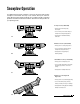
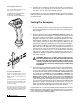
The Model 810SS control wire harness is pack-
aged with a stainless steel mount bracket (P/N
70040). Use the bracket to secure the wire har-
ness extension (vehicle) to the skid steer.
Position the bracket in the notch provided on the
molded rubber connector and mount it to the skid
steer. Locate the bracket in an accessible location
for easy on-and-off installation of the harness.