BLIZZARD POWER PLOW ® YEARS 1999 to 2003 www.blizzardplows.
Introduction Congratulations on purchasing the most advanced all-season skid steer snowplow attachment available! The Blizzard Power Plow Model 810SS is clearing new trails for innovative design, rugged durability, quality craftsmanship and superior performance. Our exclusive products are manufactured and tested in Michigan’s Upper Peninsula, the snow capital of the Midwest.
Snowplow Accessories All of the accessories pictured below are currently offered for your snowplow. See your local authorized Blizzard Dealer for pricing and availability. Visit our web site at www.blizzardplows.com to view new snowplow accessories and our latest Blizzard snowplow wearables. Auxiliary Control Harness P/N 62162 Integrate all snowplow controls into your skid steer using an optional auxiliary control harness. This 7 ft.
Warning! WARNING: Prior to operating your Power Plow snowplow, review the WARNING! label at the passenger’s side rear of the moldboard (shown below). CAUTION: Note: Read and understand all warnings indicated in this manual prior to operating the snowplow. Warnings and cautions in the manual are indicated by the icons shown to the left. WARNING 1. Properly mount the snowplow attachment prior to moving the skid steer. 2.
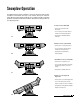
Snowplow Operation Your Blizzard Power Plow snowplow is the most advanced and versatile snowplow on the market. The easy to use controls allow you to automatically adjust the plow blade and wings into an infinite number of plowing positions. Review the illustrations below to determine the best position for your plowing needs. A. Compact Position (8' Blade Width) • Primary position when transporting the snowplow • For use in heavy snow conditions with poor visibility, initial clearing and tight quarters A.
Assembly Instructions Unpacking & Inspection Date of Purchase Dealer/Distributor Your Blizzard Power Plow snowplow has been packaged to withstand transit and weather related damage. Fully inspect all components upon receipt of your plow. In the event of shipping damage or missing parts, immediately contact our Customer Service Department at 1-888-680-8600. Begin unpacking and inspection in the following order: Telephone Number 1. Remove the shipping document from the end panel of the pallet wrap.
Moldboard Assembly 1. Begin the moldboard assembly by first removing each dust cap from both of the SLIDE BOX CYLINDERS located at the center/rear of the MOLDBOARD. Attach one 7/16"-20 x 9/16"-18 MALE O.R.B. CONNECTOR to each of the retract ports (#7 & #10) and one 9/16"-18 x 9/16"-18 MALE O.R.B. CONNECTOR to each of the extend ports (#8 & #9). Review the diagram below. Note: All of the hydraulic adapters can be found packaged with the manifold assembly.
9/16" 9/16" Male O.R.B. Connector Adapter (Port #1, #2, #8 & #9) 7/16" 9/16" Male O.R.B. Connector Adapter (Port #7 & #10) 9/16" A-frame Assembly For your convenience, the MANIFOLD and ANGLE CYLINDERS have been secured to the A-FRAME at the factory; however, each contain several components you will need to install. 1. Begin the assembly by first removing the A-FRAME COVER. Remove each of the 3/8"-16 x 1-1/2" hex cap screws and washers from the cover to gain access to the hydraulic manifold. 2.
Be careful not to overtighten the hose connections. Complete the hose installation by running each hose through the access holes in the A-frame to their respective manifold ports. 4. The PRESSURE & TANK HYDRAULIC HOSES attach to the ports on the side of the manifold labeled “P” and “T”. Verify that the 3/4" x 78" hydraulic hose with the 1-1/16"-12 female swivel is attached to the 1-1/16"-12 x 1-1/16"-12 MALE O.R.B. CONNECTOR ADAPTER located in the pressure port (“P”).
810SS Pistol Grip Control Functions There are three switches that operate all of the 810SS Power Plow blade functions: (A) DRIVE. BOX: UP-Extend, DOWN-Retract (B) ANGLE: UP-Left, DOWN-Right (C) PASS. BOX: UP-Extend, DOWN-Retract A B 4. Complete the assembly by attaching the A-frame cover. Align the holes in the cover with those on the A-frame and secure it with 3/8"-16 x 1-1/2" hex cap screws and 3/8" washers.
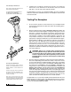
Mounting & Dismounting Instructions Prior to operating your Power Plow, review the Mounting & Dismounting Instructions label at the driver’s side rear of the moldboard (shown below). SKID STEER MOUNTING & DISMOUNTING INSTRUCTIONS MOUNTING DISMOUNTING 1. 1. Position the skid steer close to the snowplow attachment and align the mount points on the skid steer plate to those on the plow attachment plate. Lower the attachment on a flat, level surface and turn the engine off. 2.
Maintenance Schedule Maintenance Performed Date Regular Maintenance Your Blizzard Power Plow snowplow has been designed for years of rugged, dependable service with low maintenance. To ensure proper working condition, follow the maintenance guidelines below and on the next page. CAUTION: Always follow the maintenance guidelines in a timely fashion. Failure to observe maintenance guidelines may result in poor snowplow operation, increased component wear or possibly lead to part failure.
Storing Your Snowplow Annual Fluid Replacement Type & Quantity of Fluid Replaced Date Placing Your Plow In Storage 1. Position your plow on a flat, level surface for storage. Follow the dismounting procedure illustrated on page 9. 2. Pressure wash and dry the entire snowplow prior to placing in storage. 3. Apply a liberal amount of white lithium grease to the male and female electric connectors on the pistol grip wire harness. 4.
Plow Specifications Moldboard Length ......................................................................................8' Thickness ....................................................................12 Gauge Height ....................................................................................31" Reinforcement ......................................................4 Ribs @ 1/4" Cutting Edge ......................................................1/2" x 6" (1080) Finish................................
Torque Specifications Grade Identification Marking for J429 - Grade 8 Bolt • Material: Medium carbon alloy steel:quenched and tempered • Minimum Proof Strength: 120,000 psi • Minimum Tensile Strength: 150,000 psi • Core Hardness Rockwell (min.): C33, (max.
M O D E L 8 1 0 S S PA R T S L I S T Ref. No. Part Number Qty.
M O D E L 8 1 0 S S PA R T S L I S T Ref. No. Part Number Qty. Part Description 67 68 69 61366 61275 61085 2 7 1 Grommet, 1-15/16" I.D., 2-5/8" O.D.
5 6 2 46 45 44 3 40 4 41 43 42 35 39 15 18 50 51 37 8 17 50 47 49 9 14 16 13 12 11 48 49 12A 53 10 55 56 67 2003 Blizzard® Power Plow® Snowplow Assembly Schematic - Model 810SS Blizzard Corporation reserves the right, under its Continuous Improvement Policy, to change construction or design details and furnish equipment when so altered without reference to illustrations or specifications. Blizzard Corporation offers a one-year limited warranty for all snowplows and accessories.
26 25 24 20 23 22 19A 21 30 1 33 32 19 31 7 34 35 29 36 28 27 37 38 7 39 61 60 86A 59 48 71 54 49 4 55 58 57A 57 56 69 70 7 62A 62 86 87 89 68 50 60 88 65 66 50 88A 65 64 90 49 61 60 60 63 49 63 72A - SEE DETAIL ON PAGE 18.
18 Diagram - Hydraulic Manifold Detail 78 79 76 78A 78 79 77 76 80 81 75 84 79 82 38 77 76 78 84 83 76 36 75 85 78 78 74 72 73
CONNECTS TO C3 SEE SCHEMATIC ON PAGE 24. A B C D E F G H J K N/A S5 N/A N/A S4 S3 S9 S10 S1 S2 S10 S2 S4 S3 S9 S1 S5 MODEL 810SS COIL HARNESS WIRE SCHEMATIC (2003) LEFT SLIDE BOX RIGHT SLIDE BOX RIGHT ANGLE LEFT ANGLE 8 1 7 RV2 1500 PSI RV1 1700 PSI CV1 50 PSI 2 3000 PSI RV5 CV2 50 PSI 9 10 RV3 1500 PSI RV4 1700 PSI CV3 50 PSI CV4 50 PSI S2 S1 S3 S4 S10 S9 .052 S5 .
20 Diagram - Pistol Grip Control Wire Harness BLACK NYLON BRAID JACKET MATERIAL UNLESS OTHERWISE SPECIFIED ALL DIMENSIONS IN INCHES NOT DRAWN TO SCALE P/N 62082 1 2 3 4 5 6 COLOR BROWN GREEN PINK/BLACK PINK/BLACK BROWN BLUE 18 18 18 18 18 18 AWG 5 6 3 4 1 2 BACK VIEW OF SWITH #2 6" 84" 6" 6" 6" 84" LENGTH 1 2 3 4 5 6 PIN NO. A B C D E F G H J K PIN NO.
Pistol Grip Control Harness Wire Schematic 21 RIGHT ANGLE LEFT ANGLE PASS. SIDE RETRACT PASS. SIDE EXTEND SWITCH #2 SWITCH #1 BROWN BLUE/BLACK BLUE/WHITE GREEN RED/BLACK BLUE RED/WHITE BLACK BLACK PINK/BLACK 810SS PISTOL GRIP CONTROL WIRE SCHEMATIC (2003) DRIVE. SIDE RETRACT DRIVE.
22 Diagram - Wire Harness Extension (Vehicle) CONNECTS TO C1 ON PAGE 20. PINK/BLACK BROWN BLACK BLACK GREEN BLUE BLUE/BLACK BLUE/WHITE RED/BLACK RED/WHITE COLOR POWER (POSITIVE) PUMP SOLENOID GROUND (NEGATIVE) GROUND RIGHT ANGLE LEFT ANGLE DRIVE. SLIDE BOX RET. DRIVE. SLIDE BOX EXT. PASS. SLIDE BOX RET. PASS. SLIDE BOX EXT.
Wire Harness Extention (Vehicle) Wire Schematic 23 C2 810SS WIRE HARNESS EXTENSION ( VEHICLE) WIRE SCHEMATIC (2003) BLACK PINK/BLACK BROWN BLUE/BLACK BLUE/WHITE GREEN RED/BLACK BLUE RED/WHITE BLACK M1
24 Diagram - Wire Harness Extension (Plow) CONNECTS TO M1 ON PAGE 22. 18 N/A N/A N/A 18 18 N/A N/A N/A 18 18 18 N/A N/A 18 18 AWG UNLESS OTHERWISE SPECIFIED NOT DRAWN TO SCALE P/N 62134 810SS WIRE HARNESS EXTENSION PLOW SIDE (2003) 3 4 5 6 7 8 9 10 11 12 13 14 GROUND N/A N/A N/A RIGHT ANGLE LEFT ANGLE N/A N/A N/A PASS. SIDE SLIDE BOX RET. DRIVE. SIDE SLIDE BOX RET. PUMP SOLENOID N/A N/A PASS. SIDE SLIDE BOX EXT. DRIVE. SIDE SLIDE BOX EXT.
Wire Harness Extension (Plow) Wire Schematic 25 M2 BLACK 810SS WIRE HARNESS EXTENSION (PLOW) WIRE SCHEMATIC (2003) BROWN BLUE/BLACK BLUE/WHITE GREEN RED/BLACK BLUE RED/WHITE BLACK C3
26 Diagram - Coil Wire Harness END VIEW CONNECTS TO C3 ON PAGE 24. H J A B C D E F G H J K UNLESS OTHERWISE SPECIFIED ALL DIMENSIONS IN INCHES NOT DRAWN TO SCALE P/N 62161 8" N/A PUMP SOLENOID N/A N/A RIGHT ANGLE LEFT ANGLE DRIVE. SLIDE BOX RET. DRIVE. SLIDE BOX EXT. PASS. SLIDE BOX RET. PASS. SLIDE BOX EXT.
Coil Wire Harness Wire Schematic 27 C4 BLUE/BLACK BLUE/WHITE BLUE GREEN RED/BLACK RED/WHITE BLACK BROWN 810SS COIL HARNESS WIRE SCHEMATIC (2003) PUMP SOLENOID GROUND PASS. SIDE EXTEND GROUND PASS. SIDE RETRACT GROUND RIGHT ANGLE GROUND LEFT ANGLE GROUND DRIVE. SIDE EXTEND GROUND DRIVE.
28 Diagram - Auxiliary Control Harness SP–4 D6 D5 D4 D3 D2 SP–1 SP–1 SP–1 SP–1 SP–1 SP–1 BROWN RED/WHITE BROWN RED/BLACK BROWN BLUE/WHITE BROWN BLUE/BLACK BROWN BLUE BROWN GREEN PIN–B PIN–K PIN–B PIN–J PIN–B PIN–H PIN–B PIN–G PIN–B PIN–F PIN–B PIN–E 1/2" REVERSE BRAIDING 4" BLACK NYLON BRAID JACKET MATERIAL 3/8" END RING TERMINAL P/N 62072 8" UNLESS OTHERWISE SPECIFIED ALL DIMENSIONS IN INCHES NOT DRAWN TO SCALE P/N 62162 810SS AUXILIARY CONTROL HARNESS (2003)
Auxiliary Control Harness Wire Schematic 29 M2 D3 D4 D5 D6 SP-2 SP-3 SP-4 SP-5 SP-6 SP-7 D2 SP-8 BROWN - PIN B GREEN - PIN E BLUE - PIN F BLUE/BLACK - PIN G BLUE/WHITE - PIN H RED/BLACK - PIN J RED/WHITE - PIN K BLACK - PIN D 810SS AUXILIARY CONTROL HARNESS WIRE SCHEMATIC (2003) GREEN BLUE BLUE/BLACK BLUE/WHITE RED/BLACK RED/WHITE BLACK D1 SP-1 C3
Troubleshooting Guide Prior to diagnosing your Power Plow, verify that all connectors (rubber connectors, plastic electric connectors, ground and power wire terminals, coil wire and extension harnesses) are free of corrosion and are well lubricated with white lithium grease. Insuring that all connectors are in good working order will save time in determining your snowplow attachment’s service needs.
Problem Probable Cause(s) Suggested Remedy Wing will not move (continued). Cartridge valve may be contaminated or damaged. A bent or over torqued cartridge will not allow the valve to move freely inside of the cartridge. Determine a damaged cartridge valve by reversing the driver’s side and passenger’s side cartridge valves one at a time. Replace valve if necessary. Plow will not angle. Review all probable causes above. NOTE: Verify coils S3 & S4 for angle functions.
BLIZZARD POWER PLOW ® LIMITED CONSUMER WARRANTY This warranty covers defects in material and workmanship except as set forth below. WARRANTED PARTY: This warranty applies only to the “Original Purchaser” who purchased this plow from an Authorized Blizzard Dealer, for personal, family or household use. TERM OF WARRANTY: This Blizzard Power Plow snowplow is warranted for the following period: Parts and labor are warranted for one year from date of purchase.
BLIZZARD POWER PLOW ® COMMERCIAL WARRANTY This warranty covers defects in material and workmanship except as set forth below. WARRANTED PARTY: This warranty applies only to the “Original Purchaser” who purchased this plow from an Authorized Blizzard Dealer, for commercial use. TERM OF WARRANTY: This Blizzard Power Plow snowplow is warranted for the following period: Parts and labor are warranted for one year from date of purchase.
95 Airpark Boulevard Calumet, MI 49913 [888] 680-8600 [906] 482-5555 [906] 482-5445 Fax www.blizzardplows.com Blizzard, Power Plow, Blizzard Power Plow, WidePass and BucketBlade are trademarks of Blizzard Corporation. Blizzard is registered in the United States Patent and Trademark Office. The Blizzard Power Plow snowplow is protected by U.S. Patents 5,638,618; 5,899,007; 6,178,669; 6,276,076 and 6,393,737. Other patents pending. Copyright © 2003 Blizzard Corporation. All rights reserved.