
User's Manual


06 A-frame Assembly
A-frame Assembly
For your convenience, the MANIFOLD and ANGLE CYLINDERS have
been secured to the A-FRAME at the factory; however, each contain
several components you will need to install.
1. Begin the assembly by first removing the A-FRAME COVER. Remove
each of the 3/8"-16 x 1-1/2" hex cap screws and washers from the
cover to gain access to the hydraulic manifold.
2. Each of the 6 HOSE PORTS receive a HYDRAULIC ADAPTER (see
illustrations to the left). Once the adapters have been installed, con-
nect the HYDRAULIC HOSES. Route each hose grouping from the
pivot beam to the access holes located on the sides of the A-frame.
Connect the hydraulic hoses to their respective adapters on the man-
ifold. Reference the table on page 13 for proper torque specifications.
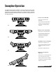
Note: All ports are identified by a stamped number on the manifold. The
numbers also identify the hydraulic functions, which can be referenced
on the label under the A-frame cover (shown below).
9/16"
9/16"
90˚ Adjustable Elbow O.R.B. Adapter
(Left & Right Angle Cylinders)
9/16" 9/16"
7/16" 9/16"
Male O.R.B. Connector Adapter
(Port #1, #2, #8 & #9)
Male O.R.B. Connector Adapter
(Port #7 & #10)
Hydraulic Valve & Hose Port
Identification Guide (Model 810SS)
NOTE: Energize the following solenoids for the functions:
1
2
7
8
9
10
Function
Right Angle - Left Cylinder
Left Angle - Right Cylinder
Left Slide Box Retract
Left Slide Box Extend
Right Slide Box Extend
Right Slide Box Retract
Port
Calumet, MI 49913
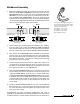
BLZ 1056
HYDRAULIC HOSES
CV2 CV4 PC
7
8
2
1
10
9
S10 S3 S4 S2
RV1 RV4
S9
RV2
RV3
RV5
S1
S5
Wing Pressure Relief Valves
Angle Pressure Relief Valve
Left Wing Pressure Relief
Left Wing Anti-Cavitation
Right Wing Anti-Cavitation
Right Wing Pressure Relief
Angle Relief
Left Wing Check Valve
Left Slide Box Check Valve
Right Wing Check Valve
Right Slide Box Check Valve
Right Slide Box Retract
Right Slide Box Extend
Angle Left - Right Cylinder
Angle Right - Left Cylinder
Left Slide Box Retract
Left Slide Box Extend
RV1
RV2
RV3
RV4
RV5
CV1
CV2
CV3
CV4
S1
S2
S3
S4
S9
S10
Function
Valve
RELIEF & CHECK VALVES
NOTE: Check valves CV1 & CV3 are not
illustrated. Both valves are located on the
opposite side of the manifold in the
diagram shown below.
The Hydraulic Valve & Hose Port Identification
Guide (right) is located under the A-frame cover.
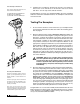
3. Next, remove each dust cap from both of the hydraulic angle cylinder
ports and attach one 9/16"-18 x 9/16"-18 90˚ ADJUSTABLE ELBOW
O.R.B. ADAPTER to each port. Note: The cylinder ports should be
facing away from the A-frame. Each adapter should be angled toward
the top of the moldboard. Review the torque specifications chart on
page 13. Connect one 3/8" x 24" hydraulic hose (P/N 60091) to each
angle cylinder adapter.