Assembly & Operation Manual Blizzard Straight Blade Snowplows Models 700LD, 760LD, 760 & 800
Introduction Congratulations on purchasing the finest straight blade snowplow available! Blizzard straight blades are clearing new trails for innovative design, rugged durability, quality craftsmanship and superior performance. Our exclusive products are manufactured and tested in Michigan’s Upper Peninsula, the snow capital of the Midwest.
Snowplow Accessories All of the accessories pictured below are currently offered for your snowplow. See your local Authorized Blizzard Dealer for pricing and availability. Visit our web site at www.blizzardplows.com to view new snowplow accessories and our latest Blizzard snowplow wearables. Straight Blade Joystick Window Mount Bracket P/N 61261 This adjustable bracket mounts easily to your straight blade joystick control and installs quickly onto any door panel.
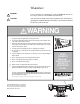
Warning! WARNING: Prior to operating your straight blade, review the WARNING! label at the passenger’s side rear of the moldboard (shown below). CAUTION: Note: Read and understand all warnings indicated in this manual prior to operating the snowplow. Warnings and cautions in the manual are indicated by the icons shown to the left. WARNING 1. Properly mount the snowplow prior to moving the vehicle. 2.
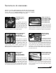
Snowplow Operation BLIZZARD ® Your snowplow is the most advanced and versatile straight blade on the market. The easy-to-use joystick control allows you to automatically adjust the plow blade into an infinite number of plowing positions. Review the illustrations below for instruction on maneuvering your snowplow. WARNING A. To prevent accidental plow activation, turn POWER switch to the “OFF” position when not in use. BLZ 1017 A.
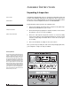
Assembly Instructions Unpacking & Inspection Date of Purchase Dealer/Distributor Your Blizzard straight blade has been packaged to withstand transit and weather related damage. Fully inspect all components upon receipt of your plow. In the event of shipping damage or missing parts, immediately contact our Customer Service Department toll free at 1-888-680-8600. Begin unpacking and inspection in the following order: Telephone Number 1. Remove the shipping document from the end panel of the pallet wrap.
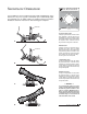
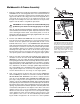
Moldboard & A-Frame Assembly 1. Begin the moldboard assembly by positioning the PIVOT BEAM and A-FRAME near the connecting points at the rear of the blade between the two center support ribs. Position the pivot beam between the two support ribs until the connecting points on the beam align with those on the plow. Insert one 3/4"-10 x 3" (2" shank) hex head cap screw through each mounting hole and secure with a 3/4"-10 top lock nut. Tighten each nut until it is snug with the pivot beam.
7/16" Hydraulic Lift / Lower Cylinder 7/16" The draw latch consists of a series of interconnected plates and pins that attach to the A-frame and the hydraulic lift cylinder. Hex Head Cap Screw (3/4"-10 x 4-1/2") or (3/4"-10 x 4") for 700LD & 760LD only Draw Pin To mount the straight blade, the A-frame latch should be lowered over the draw pin– this allows the draw latch to pull the plow into the undercarriage.
/16" 9/16" 9/16" 9/16" 90˚ Adjustable Elbow O.R.B. Adapter (Port #1) 7/16" Male Extra Long Elbow Adapter (Port #2) 9/16" 7/16" Male O.R.B. Connector Adapter & 90˚ Swivel Elbow Adapter (Ports #3 & #4) Note: The gray arrows shown on the manifold illustration above indicate the direction the 90˚ adapters should face to receive the hydraulic hoses.
Apply Loctite® To Pump Mount Hardware Upon Installation Secure one 3/8"-16 x 3/4" hex head cap screw and 3/8" flat washer through the top mount hole in the bracket and into the pump. Insert one 3/8"-16 x 1-3/4" threaded stud and 3/8"-16 jam nylon insert lock nut through the bottom mount hole in the bracket and into the pump. The threaded stud should bottom out in the pump. Note: A medium strength threadlocker, such as Loctite® 242® should be used on both of the pump mount fasteners.
Electrical Assembly - Plow Harness 1. Begin the electrical assembly by connecting the RED POWER WIRE from the PLOW ELECTRICAL HARNESS to the PUMP motor terminal stud using the hardware provided on the pump. 2. Place one 3/8" INTERNAL/EXTERNAL TOOTH LOCK WASHER, the BLACK GROUND WIRE (from the harness) and the RED GROUND WIRE on the COIL WIRE HARNESS (from the manifold) over the tapped hole on the pump and secure the ground using one 3/8"-16 x 3/4" hex head cap screw. 3.
A Electrical Assembly - Vehicle Harness B CAUTION: Always perform the vehicle wire harness assembly with the vehicle off and the keys out of the ignition. Use caution when testing the electrical wires for the vehicle’s headlight functions.
7. Next, remove the front directional light assembly on the driver’s side of the vehicle. Feed the VIOLET, turn light wire and GRAY, run light wire from the main lighting harness through the opening in the directional light housing. At this point, use a test light or ohm meter to determine the proper wires in the vehicle’s electrical system to splice into. Once you have identified the proper wires, position one end of the turn or run light wire into a SPLICE LOCK CONNECTOR provided.
12. Connect the RED POWER WIRE (with 10 AMP FUSE) to a switched power source with a minimum of 10 amps. Note: The red power wire MUST be fused and switched on and off with ignition. Secure all loose wires under the dash. Dome Plug Apply a thin bead of silicone around the inside perimeter of the polyethylene dome plugs prior to capping the light tower ends. The silicone will help retain the dome plug inside of the headlight mount tube. 13. Next, install the LIGHT TOWER.
2. Raise the DRAW LATCH on the snowplow by pushing and holding the toggle switch on the A-frame upward into the “CONNECT” position. Notice the action of the fluid in the reservoir. By activating the initial hydraulic function, the fluid begins to fill the system. Push and hold the toggle switch in the “DISCONNECT” position, the draw latch will lower. Refill the reservoir until the fluid is 3/4" from the top of the tank. 3.
Mounting & Dismounting Instructions Prior to operating your straight blade, review the Mounting & Dismounting Instructions label at the driver’s side rear of the moldboard (shown below). MOUNTING & DISMOUNTING INSTRUCTIONS TM A-Frame Latch Lock Pin MOUNTING 1. Position vehicle close to the plow and align mounting points on the undercarriage and A-frame. Verify that the plow kickstand is in the lowered position. Turn vehicle ignition off. 2.
Regular Maintenance Maintenance Schedule Maintenance Performed Date Your Blizzard straight blade snowplow has been designed for years of rugged, dependable service with low maintenance. To ensure proper working condition, follow the maintenance guidelines below and on the next page. CAUTION: Always follow the maintenance guidelines in a timely fashion. Failure to observe maintenance guidelines may result in poor snowplow operation, increased component wear or possibly lead to part failure.
Annual Fluid Replacement Type & Quantity of Fluid Replaced Date Storing Your Snowplow Placing Your Plow In Storage 1. Position your plow on a flat, level surface for storage. Follow the dismounting procedure illustrated on page 14. 2. Pressure wash and dry the entire snowplow prior to placing in storage. 3. Apply a liberal amount of dielectric grease to all electrical plugs and connections. Clean and install all dust caps. 4.
Plow Specifications Moldboard Length 700LD ..................................................................................7'-0" 760LD ..................................................................................7'-6" 760 ......................................................................................7'-6" 800 ......................................................................................8'-0" Thickness ........................................................................
M O D E L S 7 0 0 L D , 7 6 0 L D , 7 6 0 & 8 0 0 PA R T S L I S T Ref. No. Part No.
M O D E L S 7 0 0 L D , 7 6 0 L D , 7 6 0 & 8 0 0 PA R T S L I S T Ref. No. Part No.
M O D E L S 7 0 0 L D , 7 6 0 L D , 7 6 0 & 8 0 0 PA R T S L I S T Ref. No. Part No.
M O D E L S 7 0 0 L D , 7 6 0 L D , 7 6 0 & 8 0 0 PA R T S L I S T Ref. No. Part No.
3 2 10 17 18 20 19 12 13 14 21 31 33 31 15 30 32 21 4 5 32 23 8 7 6 16 28 24 6A 5 29 24A 25 45 48 49 65 51 34 35 36 37 27 4 5 39 40 41 31 44 26 110 43 109 108 107 107A 42 109A 59 58 57 32
86 9A 85 9 11 Straight Blade Snowplow Assembly Schematic - Models 700LD, 760LD, 760 & 800 Blizzard Corporation reserves the right, under its Continuous Improvement Policy, to change construction or design details and furnish equipment when so altered without reference to illustrations or specifications. Blizzard Corporation offers a one-year limited warranty for all snowplows and accessories.
RIGHT ANGLE 1 3000 PSI 3 2 RAISE LOWER RV FC S5 S6 S3 CONNECTS TO M5 SEE SCHEMATIC ON PAGE 27. LIFT CYL. LEFT ANGLE S7 4 A B C D E F G H J K S5 S7 S6 S8 S4 S3 N/A N/A N/A N/A S4 S6 S8 S3 S5 S7 S8 S4 TGP PGP T1 P1 100 100 99 99 102 103 105 104 98 96 106 99 99 106 99 101 92 93 98 94 94 97 96 36 24 Manifold Detail w/Hyd. & Elec.
WIRE COLOR (BLUE) BLIZZARD HARNESS PLUG (VEHICLE) UNIVERSAL 14 + 2 MOLD PIN NO.
Diagram - Plow Harness ORANGE/WHITE WHITE ORANGE CAVITY PLUG ORANGE/RED ORANGE/BLACK 3" 5 8 VIEW FRONT 6 2 1 B1 3" BLACK UNLESS OTHERWISE SPECIFIED ALL DIMENSIONS IN INCHES NOT DRAWN TO SCALE WITH MOLDED PLUG P/N 62039 PLOW HARNESS (2002) RED M5 8" B2 PLASTIC ELECTRIC CONNECTOR, FEMALE - P/N 62046 SILICONE RUBBER CABLE SEAL - P/N 62096 FEMALE TERMINAL (18-16 AWG) - P/N 62093 M10 OTTO CONNECTOR AMP TERMINALS (18-14 AWG) (TWO 18-14 AWG) (4) ORANGE/RED (2) BROWN (1) BROWN (3) WHITE
Plow Harness Wire Schematic 27 K J H G F E D C B A M5 ORANGE/BLACK = A ORANGE/RED = B NOT USED = C ORANGE = D WHITE = E ORANGE/WHITE = F 6 7 6 7 PINK/BLACK 1 3 2 4 DPDT (ON)-OFF-(ON) S1 6 5 HITCH SWITCH BLUE/BLACK BLUE/WHITE RED/BLACK RED/WHITE J RED/BLACK K RED/WHITE GREEN BLUE RED BROWN RED/WHITE RED/BLACK BLUE/WHITE BLUE/BLACK PLOW HARNESS WIRE SCHEMATIC (2002) BLUE H BLUE/WHITE NOTE: WHITE IS ON TOP TERMINAL 8 5 8 4 5 3 3 4 2 2 BROWN WHITE WHITE ORANGE/RED
Diagram - Main Lighting Harness E A B RUN (GRAY-1) TURN (VIOLET) OTHER WIRE GREEN/RED GREEN/RED YELLOW/RED YELLOW/RED WHITE WHITE UNLESS OTHERWISE SPECIFIED ALL DIMENSIONS IN INCHES NOT DRAWN TO SCALE RELAY VERSION P/N 62113 YELLOW/BLACK YELLOW/BLACK F 24" F 28" 18" WHITE/RED WHITE LT. GREEN YELLOW LT. GREEN/RED YELLOW/RED LT. GREEN/BLACK YELLOW/BLACK GRAY VIOLET PINK COLOR ALTERNATIVE B SPLICE 18" ALTERNATIVE A DOUBLE TERMINATE LT. GREEN/BLACK LT.
Main Lighting Harness Wire Schematic 29 LEFT TURN VIOLET GRAY PE 4D 5C 6 N/A 4D 5C 6 N/A 6 N/A = NOT USED 1 2 3 4 5 GROUND (-) VEHICLE HARNESS LT. GREEN/BLACK WHITE GREEN/YELLOW BLACK/WHITE (HIGH) NOTE: CONNECTORS M14 TO M17 ARE SIX PRONG SQUARE RUBBER FEMALE YELLOW/BLACK WHITE GRAY NO 3P/DT2/ST1 RELAY (DIODE LOCATED INSIDE OF RELAY) (LOW) WHITE LT. GREEN/BLACK YELLOW/BLACK GRAY VIOLET (GROUND) 2A 3F 4D 5C 6 N/A 2A 3F 4D 5C 6 N/A 1 2 3 4 5 GRAY LT.
30 Diagram - Vehicle Harness 9 13 4 1 14 15 10 6 2 16 7 11 8 LT. G 9 8 7 NYLON BRAID RED WITH BLACK & WHITE STRIPE JACKET MATERIAL 30" 3 100" LONG CONNECTS TO M1 PIN #3 BROWN/WHITE AWG 18 A2 (4) SUPPLIED LOOSELY P/N 62072 3/8" RING TERMINAL 82" TO PUMP SOLENOID 82" A1 3 6 9 12 1 2 LOOKING AT CONNECTOR END VIEW LOOKING AT CONNECTOR END VIEW 2 5 8 11 RELAY GROUND N/A FUNCTION 18 18 18 18 18 18 18 18 18 18 18 18 AWG 18 N/A AWG “MOLEX” FREE HANGING RECEPTACLE .
Vehicle Harness Wire Schematic 31 N/A M1 NEG POS PUMP SOL. RIGHT BOX EXT. RIGHT BOX RET. LEFT BOX EXT. LEFT BOX RET.
32 Diagram - On/Off Switch Leads & Ground COLOR GREEN/YELLOW GREEN/YELLOW PIN NO.
Torque Specifications Grade Identification Marking for J429 - Grade 8 Bolt • Material: Medium carbon alloy steel:quenched and tempered • Minimum Proof Strength: 120,000 psi • Minimum Tensile Strength: 150,000 psi • Core Hardness Rockwell (min.): C33, (max.
Troubleshooting Guide Prior to diagnosing your straight blade, verify that all connectors (plow and vehicle wire harness plugs, headlight adapters, control box, fused hot lead, draw latch switch, solenoid ground wire connection, coil wire lead harness, plow headlight harnesses) are free of corrosion and are well lubricated with dielectric grease. Insuring that all connectors are in good working order will save time in determining your snowplow’s service needs.
Problem Probable Cause(s) Suggested Remedy Plow will not lift. Pump works properly. (Continued from page 34.) Coils on the manifold may be damaged. Remove both S6 & S7 coils from the cartridge valves. Position a screwdriver inside of the coil and push the draw latch connect/disconnect toggle switch upward. The screwdriver should be magnetically drawn to the coil. Replace the coil if there is no action. Plow will not lift with magnification to the S6 & S7 coils. Hydraulic lock in the manifold.
BLIZZARD ® LIMITED CONSUMER WARRANTY This warranty covers defects in material and workmanship except as set forth below. WARRANTED PARTY: This warranty applies only to the “Original Purchaser” who purchased this plow from an Authorized Blizzard Dealer, for personal, family or household use. TERM OF WARRANTY: This Blizzard straight blade snowplow is warranted for the following period: Parts and labor are warranted for one year from date of purchase.
BLIZZARD ® COMMERCIAL WARRANTY This warranty covers defects in material and workmanship except as set forth below. WARRANTED PARTY: This warranty applies only to the “Original Purchaser” who purchased this plow from an Authorized Blizzard Dealer, for commercial use. TERM OF WARRANTY: This Blizzard straight blade snowplow is warranted for the following period: Parts and labor are warranted for one year from date of purchase.
95 Airpark Boulevard Calumet, MI 49913 [888] 680-8600 [906] 482-5555 [906] 482-5445 Fax www.blizzardplows.com Blizzard and Power Hitch are trademarks of Blizzard Corporation. Blizzard is registered in the United States Patent and Trademark Office. Loctite and 242 are registered trademarks of Loctite Corporation, USA. Velcro is a registered trademark of Velcro Industries B.V. Ford is a trademark of Ford Motor Company. Chevrolet, GM and Silverado are registered trademarks of General Motors Corporation.