
user manual


08 Moldboard & A-frame Assembly (cont.)
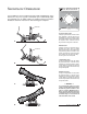
Secure one 3/8"-16 x 3/4" hex head cap screw and 3/8" flat washer
through the top mount hole in the bracket and into the pump. Insert
one 3/8"-16 x 1-3/4" threaded stud and 3/8"-16 jam nylon insert lock
nut through the bottom mount hole in the bracket and into the pump.
The threaded stud should bottom out in the pump. Note: A medium
strength threadlocker, such as Loctite® 242® should be used on both
of the pump mount fasteners.This will help prevent the fasteners from
working free.
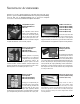
8. Once the pump and manifold assembly is in place, connect the
hydraulic hoses to their respective adapters on the manifold. Remember,
the labeling on the hydraulic hoses correspond with the stamped
numbers on the manifold.
Begin installing the hoses with the driver’s side raise cylinder hose (#3).
Attach the straight end of the hose to the 7/16"-20 x 9/16"-18 90˚
swivel elbow adapter on the manifold. Connect the passenger’s side
lower cylinder hose to Port #4. Loop the hose through the opening in
the A-frame and connect the straight end of the hose to the 7/16"-20
90˚ swivel elbow adapter. Run both angle cylinder hoses (#1 and #2)
over the A-frame angle and to their respective manifold ports. Note:
The lift cylinder hoses should be routed through the triangular openings
in the A-frame.
9. Next, secure the manifold to the A-frame. Remove both 3/8" flat washers,
3/8" split lock washers and 3/8"-16 x 1" hex head cap screws from the
manifold and align the mount holes with the A-frame brackets. Position
the DIODE PACK MOUNT BRACKET against the outside of the A-
frame bracket on the driver’s side. Note: Both of the prongs should be
facing up. Align the outside hole on the diode bracket with the holes
on the A-frame and manifold. Properly replace and tighten all hardware.
Note: A medium strength threadlocker, such as Loctite® 242® should
be used to secure the manifold mount fasteners.
10. Hook each EXTENSION SPRING to the receiving holes located on
the pivot beam and connect the opposite end of the spring to their
respective SPADE BOLTS. Install the 5/8"-11 x 5" spade bolts through
the EXTENSION SPRING MOUNTING ANGLE on the top rear of the
blade. Secure each spade bolt by placing one 5/8" flat washer on the
bolt and thread one 5/8"-11 nylon insert lock nut. Tighten each lock nut
until a piece of paper can pass between the 3th & 4th coils on the spring.
11. Install the flexible BLADE GUIDES at each end of the moldboard.
Insert the 5/16"-18 x 1" hex head cap screw through the holes provided
at the top of the outside reinforcement rib.Tighten all screws using the
nylon insert lock nuts provided.
Congratulations! You have successfully completed half of the installation.
Don’t quit now, you’re nearly out of the garage!
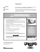
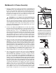
A medium strength threadlocker, such as Loctite®
242®, should be used to properly secure the
mount hardware for the pump and manifold.This
will help prevent the hardware from working free
from vibration and plow use. Apply a liberal
amount of threadlocker to both threaded fasten-
ers and the threads in the pump (top diagram).
The manifold receives two 3/8"-16 x 1" hex cap
screws—one on each side of the A-frame. Like-
wise, use threadlocker on these fasteners and
the tapped holes in the manifold (bottom diagram).
Use Loctite® on
Manifold Mount
Hardware
Apply Loctite®
To Pump Mount
Hardware Upon
Installation