CONTROL INFORMATION OPERATION AND PROGRAMMING GUIDE FOR BLODGETT OVEN CONTROLS BLODGETT OVEN COMPANY www.blodgett.com 44 Lakeside Avenue, Burlington, Vermont 05401 USA Telephone (800) 331Ć5842, (802) 860Ć3700 Fax: (802)864Ć0183 PN 36025 Rev F (7/07) E 2003 - G.S.
TABLE OF CONTENTS 1. CONVECTION OVEN CONTROLS Solid State Manual Control . . . . . . . . . . . . . . . . . . . . . . . . . . . . . . . . . . . . . . . . . . . . . . . . . . . . . . . . . Cook and Hold Control . . . . . . . . . . . . . . . . . . . . . . . . . . . . . . . . . . . . . . . . . . . . . . . . . . . . . . . . . . . . Blodgett IQ2T Control . . . . . . . . . . . . . . . . . . . . . . . . . . . . . . . . . . . . . . . . . . . . . . . . . . . . . . . . . . . . Pulse Plus . . . . . . . . . . . . . . .
TABLE OF CONTENTS This page intentionally left blank.
CHAPTER 1 CONVECTION OVEN CONTROLS 1-1
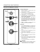
CONVECTION OVEN CONTROLS SOLID STATE MANUAL CONTROL CONTROL DESCRIPTION 1 1. SELECTOR SWITCH - controls power to the oven for cook or cool down. OVEN OFF COOL DOWN 2. BLOWER SWITCH - controls blower speed, either hi or lo. Two speed not available in 50 Hz. COOK 3. LIGHTS SWITCH - controls interior lights. ON HI 2 OFF LO LIGHTS BLOWER 60 Hz Only 3 4. OVEN READY LIGHT - when lit indicates burner operation. When the light goes out the oven has reached operating temperature. 5.
OPERATION & CALIBRATION COOK AND HOLD CONTROL CONTROL DESCRIPTION 1 1. SELECTOR SWITCH - controls power to the oven for cook, cook & hold, and cool down. OVEN OFF COOL DOWN 2. LIGHTS SWITCH - controls interior lights. COOK 3. OVEN READY LIGHT - when lit indicates burner operation. When the light goes out, the oven has reached operating temperature. COOK & HOLD 4. COOK THERMOSTAT - controls oven temperaĆ ture in the cook cycle. 2 ON OFF LIGHT OFF OVEN READY 3 5.
CONVECTION OVEN CONTROLS OPERATION Cook and Hold: Cook Only: 1. Turn the SELECTOR SWITCH (1) to COOK. The blower and control compartment cooling fans operate and are controlled automatically by the action of the doors. 1. Turn the SELECTOR SWITCH (1) to COOK. The blower and control compartment cooling fans operate and are controlled automatically by the action of the doors. 2. Set the COOK THERMOSTAT (4) to the desired temperature. 3. Preheat until the OVEN READY LIGHT (3) goes out. 4.
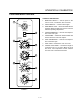
OPERATION & CALIBRATION BLODGETT IQ2T CONTROL COMPONENT DESCRIPTION 1. OVEN POWER SWITCH - controls power to the oven. 2. TOP DISPLAY - displays temperature and other controller related information. 3. FAN HI LED - when lit indicates the fan is runĆ ning at high speed. 4. BOTTOM DISPLAY - displays cook time and other controller related information. 5. PROG LED - when lit indicates the controller is in the programming mode. 6. HEAT LED - when lit indicates the control is callĆ ing for heat. 7.
CONVECTION OVEN CONTROLS OVEN OPERATION Oven Startup: 1. Toggle the POWER SWITCH (1) to ON. The oven preheats to the lowest programmed first stage temperature. The LEDS (16) for all products with the same first stage temperature light. While the unit preheats the TOP DISPLAY (2) gives the set temperature. The BOTTOM DISĆ PLAY (4) reads Lo if the oven is more than 10_ beĆ low setpoint. When the oven reaches 10_ of the preheat temperature an alarm sounds and the bottom display reads Ready.
OPERATION & CALIBRATION 4. The top display reads SHLF. The bottom display gives the numbers of the shelves that have been assigned. Within five seconds the shelf with the least amount of time remaining is displayed. The led for the product with the least time remaining flashes faster than the led for the other products. NOTE: To view the remaining cook time for the other products press and hold the SCAN KEY (15). The bottom display cycles through the remaining cook times for each product.
CONVECTION OVEN CONTROLS 1. The top display reads CYC1. The bottom display gives the current fan cycle. Press the TOGGLE/ CLEAR KEY (11). The bottom display toggles beĆ tween PULS, HEAt and FULL. 2. If heat or full are selected press the SCAN KEY (15) to save the new fan cycle and advance to timing mode. If pulse is selected press the SCAN KEY (15) and continue with Steps 3-4 to program the pulse cycle. 3. The top display reads on-1. The bottom display gives the current pulse on time.
OPERATION & CALIBRATION PROGRAMMING MULTIPLE STAGE RECIPES Entering the Programming Mode: 1. Press and hold the PROG KEY (10). The top disĆ play reads CodE. NOTE: Repeat Steps 1-2 to program the cook temperature for additional stages. When the cook temperature for the final stage has been entered the top display reads Ct-1. 2. Use the product keys to enter the programming access code: 3 1 2 4. Press the ENTER KEY (14). The top display reads Prod. 3.
CONVECTION OVEN CONTROLS control advances to the next stage programmed for the pulse fan option. NOTE: Repeat Steps 4-5 to program cycle times for all pulse fan stages. When the final pulse off time has been entered the control advances to timing mode. Programming the Timing Mode: NOTE: It may be necessary to press the ENTER KEY (14) until the top display reads tC-1. There are 2 options for timing mode: Straight and Flex. 1. The top display reads tC-1. The bottom display gives the current timing mode.
OPERATION & CALIBRATION Programming the setback mode The setback mode operates as a power saving feaĆ ture. After a period of nonĆuse (the setback time) the oven temperature automatically decreases to the setback temperature. The oven will maintain this temperature until a product key is pressed. The miniĆ mum setback time is 20:00. 1. The top display reads SEtb. The bottom display gives the setback mode. To change the setback press the TOGGLE/CLEAR KEY (11). The botĆ tom display toggles between YES and no.
CONVECTION OVEN CONTROLS FACTORY LEVEL PROGRAMMING Enabling/Disabling the fan error detection circuit Entering the programming mode 1. The top display reads FanC. The bottom display reads YES or NO. 1. Press the program key. The top display reads CodE. 2. Use the product keys to enter the factory proĆ gramming accss code: 4 5 2 3. Press the enter key. The top dislay reads Fact. Programming the oven configuration 2. Press the TOGGLE/CLEAR KEY to toggle beĆ tween choices. 3.
OPERATION & CALIBRATION PULSE PLUS CONTROL DESCRIPTION 1 COOL DOWN 3 1. SELECTOR SWITCH - controls power to the oven for cook or cool down. 2. BLOWER SWITCH - controls blower speed, eiĆ ther hi or lo. Two speed not available in 50 Hz. 3. LIGHTS SWITCH - controls interior lights. 4. AMBER FAN DELAY LIGHT - indicates the oven is in pulse plus. 5. FAN DELAY TIMER - activates pulse plus for 0Ć10 minutes. The blower and burners pulse on for 30 seconds and off for 30 seconds for the duration of time set. 6.
CONVECTION OVEN CONTROLS HUMIDAIRE CONTROL DESCRIPTION 1 1. SELECTOR SWITCH - controls power to the oven for cook or cool down. 2. LIGHTS SWITCH - controls interior lights. 3. OVEN READY LIGHT - when lit indicates burner operation. When the light goes out, the oven has reached operating temperature. 4. SOLID STATE THERMOSTAT Ć allows either 8 preĆset temperatures to be selected in accorĆ dance with customer requirements, or an infinite selection of temperatures from 200Ć500_F (95Ć260_C).
OPERATION & CALIBRATION ZEPHAIRE CONTROL - SINGLE SPEED BLOWER CONTROL DESCRIPTION 1 ON MAN OFF AUTO BLOWER COOL DOWN 1. BLOWER ON/OFF SWITCH - Controls the opĆ eration of the blower. If the blower switch is in the OFF position the oven will be turned off. 2 2. COOL DOWN SWITCH - When the switch is in the AUTO position, the oven can be used to cook. When the switch is in the MAN position, the oven is cooling down for the next bake. 3 3.
CONVECTION OVEN CONTROLS ZEPHAIRE CONTROL - SINGLE SPEED BLOWER WITH CAVITY LIGHTS CONTROL DESCRIPTION 1 2 ON ON MAN OFF OFF AUTO LIGHTS BLOWER 1. CAVITY LIGHTS ON/OFF - Operates the oven cavity lights. 3 2. BLOWER ON/OFF SWITCH - Controls the opĆ eration of the blower. If the blower switch is in the OFF position the oven will be turned off. COOL DOWN 3. COOL DOWN SWITCH - When the switch is in the AUTO position, the oven can be used to cook.
OPERATION & CALIBRATION ZEPHAIRE CONTROL - DUAL SPEED BLOWER CONTROL DESCRIPTION 1 HI OFF LOW BLOWER MAN 1. BLOWER HI/LO/OFF SWITCH - Controls the opĆ eration of the blower. If the blower switch is in the OFF position the oven will be turned off. 2 AUTO COOL DOWN 2. COOL DOWN SWITCH - When the switch is in the AUTO position, the oven can be used to cook. When the switch is in the MAN position, the oven is cooling down for the next bake. 3 3.
CONVECTION OVEN CONTROLS ZEPHAIRE CONTROL - DUAL SPEED BLOWER WITH CAVITY LIGHTS CONTROL DESCRIPTION 1 HI ON OFF OFF 2 LOW LIGHTS BLOWER MAN 1. CAVITY LIGHTS ON/OFF - Operates the oven cavity lights. 3 AUTO 2. BLOWER HI/LO/OFF SWITCH - Controls the opĆ eration of the blower. If the blower switch is in the OFF position the oven will be turned off. COOL DOWN 3. COOL DOWN SWITCH - When the switch is in the AUTO position, the oven can be used to cook.
OPERATION & CALIBRATION SOLID STATE DIGITAL CONTROL CONTROL DESCRIPTION 1. SELECTOR SWITCH - turns power to the oven on or off. Allows selection of Cook or Cool Down Modes and fan speed (if applicable). 2. DISPLAY - displays time or temperature and other information related to oven function. 3. HEAT LAMP - lights when heater is on. 4. PULSE LAMP - lights when Pulsed Fan Mode is turned on. 5. HOLD LAMP - lights when Hold Mode is turned on. 6. DIAL - used to enter set points in display 7.
CONVECTION OVEN CONTROLS 2. Rotate DIAL (6) to enter the pulse time. Pulse time is a portion of the preĆset cook time. OPERATION Cook Only: 1. Turn the SELECTOR switch (1) to the desired poĆ sition. 2. Enter the cook time and temperature. 3. Load product into the oven. NOTE: The display reads LOAD when the oven is near the set temperature. 4. Press the START/STOP key (7). The timer begins to count down. 5. When the cook timer reaches 00:00 the buzzer sounds and the display reads DONE. 6.
OPERATION & CALIBRATION Cook with Pulse: 2ND LEVEL PROGRAMMING NOTE: PULSE light is on when pulse mode is on and off when pulse mode is off. To Initiate Programming 1. Turn the SELECTOR SWITCH (1) to the desired position. 1. Set the time to 1 minute. 0:01 01:00 2. Set the temperature to 151_F (66_C). 2. Enter cook time and cook temperature. To Access Second Level Programming 3. Press PULSE KEY (11). Enter the pulse time. 1. Press and hold the TEMPERATURE key and the START/STOP key simultaneously.
CONVECTION OVEN CONTROLS To Return to Normal Operating Mode SETTING THE DISPLAY SCALES 1. Press the TEMPERATURE key. DIGITS 1ST 2ND 3RD 2. The control goes through self check then disĆ plays the set temperature 151_F (66_C). 4TH 3. The oven can now be controlled as normal.
OPERATION & CALIBRATION CHĆPRO3 (SOLID STATE PROGRAMMABLE DIGITAL CONTROL) COMPONENT DESCRIPTION 1. SELECTOR SWITCH - turns power to the oven on or off. Allows selection of cook or cool down modes and fan speed (if applicable). 2. TIME DISPLAY - gives cook time. 3. TIME ARROW KEYS - press to enter cook and/or pulse times. 1 4. READY INDICATOR - when lit indicates the oven has reached the setpoint temperature and product may be loaded. 5. TEMPERATURE DISPLAY - gives cook and hold temperatures. 2 6.
CONVECTION OVEN CONTROLS MANUAL OPERATION time display resets to 00:00 then begins to count up the hold time. The fan cycles with heat deĆ mand in the hold mode. NOTE: Press the arrow keys to change the cook time and temperature at any point during manual operation. 8. Press the STOP KEY (15) to stop the timer. Cook Only: 9. Remove the product. 1. Turn the SELECTOR SWITCH (1) to the desired position. 10. Push the HOLD KEY (8) to turn off hold mode. 2.
OPERATION & CALIBRATION PROGRAMMING THE MANUAL KEY DEFAULT PROGRAMMING THE PRODUCT KEYS 1. Turn the SELECTOR SWITCH (1) to the desired position. 1. Turn the SELECTOR SWITCH (1) to the desired position. 2. Press the MANUAL KEY (12). The manual and fan key LEDs light. 2. Press the desired PRODUCT KEY (11). The product and fan key LEDs light. 3. Press the TIME ARROW KEYS (3) to enter the cook time. 3. Press and hold the PROGRAM KEY (14) until the corresponding LED flashes, approximately five seconds.
CONVECTION OVEN CONTROLS INTELLIPLUS WITH CHAIN EVENT CONTROL CONTROL DESCRIPTION 1. SELECTOR SWITCH - controls power to the oven for cook or cool down. 2. LIGHTS SWITCH - controls interior lights. 3. OVEN READY LIGHT - when lit indicates burner operation. When the light goes out the oven has reached operating temperature. 4. DIGITAL DISPLAY - displays the time, temperaĆ ture, and controller related information. 1 5. TIME DIAL - used to set the cook and/or hold time of the selected program. 2 6.
OPERATION & CALIBRATION COOK OPERATION MANUAL COOK AND HOLD OPERATION 1. Rotate the TEMPERATURE dial (6) to the desired cooking temperature from 150Ć500_F (66Ć260_C). Turn the dial clockwise to increase the temperature, counterĆclockwise to decrease. 1. Rotate the TEMPERATURE dial (6) to the desired cook temperature from 150Ć500_F (66Ć260_C). Turn the dial clockwise to increase the temperaĆ ture, counterĆclockwise to decrease. 2. Press the COOK HI/LO FAN key (9) until the disĆ play (4) reads HIFAN.
CONVECTION OVEN CONTROLS CHAIN EVENT PROGRAMMING SELECTING A PROGRAM NOTE: Program keys 1 and 2 can have up to six events. Program keys 3Ć5 can have up to 4 events. 1. To select a program sequence, press the desired PGM # key (11). PGM # will be illuminated. At this time the oven begins to heat up to the cook temperature stored in the event #1 chain. EI is ilĆ luminated and the E1 options are displayed. The amount of time displayed is the sum total time of all the programmed events. 1.
OPERATION & CALIBRATION 2ND LEVEL PROGRAMMING NOTE: Time must be zeroed out in order to perform the following functions. Changing Minutes to Seconds or Hours to Minutes 1. Set the temperature dial to 230_. 2. Push and hold the START TIMER until the display changes from MIN to HR. Setting a temperature offset 1. Set the temperature dial to 210_. 2. Push and hold the CANCEL and START TIMER keys until the display reads 000.UPO 3. Enter the desired offset. 4. Push the ACTUAL TEMP key.
CONVECTION OVEN CONTROLS INTELLITOUCH COMPONENT DESCRIPTION 1. SELECTOR SWITCH Ć controls power to the oven and selects cool down mode. 1 2. FUSES Ć provide oven circuit protection 3. DISPLAY Ć displays the time, temperature and controller related information. 2 4. HEAT ON LIGHT Ć indicates heat is on in the oven. 5. READY LIGHT Ć indicates the oven is ready to load. 3 4 6. PROGRAM MODE LIGHT Ć indicates oven is in program mode. 6 7. PROD Ć 7 programmable product keys. 5 8.
OPERATION & CALIBRATION PROGRAMMING SEQUENCE OPERATION 1. Press the ENTER key (9). The display reads CODE and the program lamp lights. NOTE: Multiple product keys may be in operation at the same time as long as the temperatures within these programs are the same. 2. Enter the code sequence 1Ć7Ć8Ć0 to activate the programming mode. PIC1 will be displayed. 3. Press the PROD key (7) to be programmed. 4. Key in the desired temperature if different than that shown in the display. Press the ENTER (9) key. 5.
CONVECTION OVEN CONTROLS 2ND LEVEL PROGRAMMING 4. The #2 LED illuminates To access 2nd level programming 5. Repeat steps 1Ć3 for each parameter. When the final parameter setting is entered and saved the #1 LED illuminates. 1. Turn the oven off. 2. Locate the 3 pin header on the bottom right side of the control. Move the jumper from the middle and bottom pins to the middle and top pins exĆ posing the bottom pin. 3. Turn the oven on. The program LED (1) lights.
OPERATION & CALIBRATION INTELLITOUCH II CONTROL CONTROL DESCRIPTION 1. POWER ON SWITCH - controls power to the oven. 2. LIGHTS SWITCH - controls interior lights. 3. DISPLAY - displays controller related informaĆ tion. 4. HEAT LIGHT - illuminates when the oven is heating. When the light goes out, the oven has reached operating temperature. 2 5. PROG/ENTER - used to select the programĆ ming mode, cycles through the programming options and stores programmed values into memory. Starts timer in manual mode.
CONVECTION OVEN CONTROLS PROGRAMMING PROCEDURE NOTE: Use the shelf keys (15) to enter a numeric valĆ ue. Use product keys (14) P for the numeral 9 and O for the numeral 0. 1. Set the POWER ON/OFF switch (1) to ON. The display reads OFF. 2. Press the POWER ON/OFF key (7) to power the controller. The display reads SELECT. 3. Press the PROG/ENTER key (5). 4. When the controller displays CODE-? enter the manager's code and press the PROG/ENTER key (5). The display reads -PROM-?.
OPERATION & CALIBRATION MANUAL COOKING PROCEDURE PROGRAMMED COOKING PROCEDURE NOTE: Use the shelf keys (15) to enter a numeric valĆ ue. Use product keys (14) P for the numeral 9 and O for the numeral 0. 1. Press the POWER ON/OFF key (7) to set the conĆ troller to the select state. 1. Set the POWER ON switch (1) to the ON position. 2. When the control displays SELECT press the MANUAL/COOK & HOLD key (13) to enter manuĆ al āmode. The control displays MANUAL. 3.
CONVECTION OVEN CONTROLS 2ND LEVEL PROGRAMMING ALL CONTROLS Computers with ON/OFF key in control Temperature display scale 1. Place the control in OFF mode. 1. The display flashes _F/_C then MODE-? 2. Press the CLEAR key. 2. Press any key to toggle the scale from _F to _C. 3. Press the B, A, K, and E keys followed by the PROG/ENTER key. 3. Press the PROG/ENTER key to lock in new scale. 4. The display reads ACCESS. 4. The display flashes T'_F ( or T'_C). Ready Band 5.
OPERATION & CALIBRATION BLODGETT IQT CONTROL COMPONENT DESCRIPTION 1. OVEN POWER SWITCH - controls power to the oven. 2. TOP DISPLAY - displays temperature and other controller related information. 3. PROG LED - when lit indicates the controller is in the programming mode. 4. FAN HI LED - when lit indicates the fans are runĆ ning at high speed. 5. BOTTOM DISPLAY - displays cook time and other controller related information. 6. HEAT LED - when lit indicates the control is callĆ ing for heat. 7.
CONVECTION OVEN CONTROLS OVEN OPERATION Multiple Batch Cooking Procedure: Oven Startup: This procedure is for single stage recipes with the same cook temperature and fan speed only. 1. Toggle the POWER SWITCH (1) to ON. The oven preheats to the lowest programmed first stage temperature. The LEDS (15) for all products with the same first stage temperature light. While the unit preheats the TOP DISPLAY (2) gives the actual temperature.
OPERATION & CALIBRATION 8. Press the PRODUCT KEY (16) to silence the alarm. Remove the product. Using PreAlarms: 1. The top display reads AX__. NOTE: A indicates the alarm function. X is the prealarm number. __ is the alarm time. The LED for the active product key flashes. All other LEDS are off. The function keys are disabled. 2. If a manual PreAlarm is activated, press the prodĆ uct key to silence the alarm.
CONVECTION OVEN CONTROLS Oven Cool Down: PROGRAMMING SINGLE STAGE RECIPES 1. Close the oven door. Press the COOL DOWN KEY (8). Entering the Programming Mode: NOTE: Cool down cannot be activated with the oven door open. Once the cool down cycle has beĆ gun the doors may be opened to speed the cooling process. 1. Press the PROG KEY (9). The top display reads CodE. 2. Use the product keys to enter the programming access code: 3 1 2 4. Press the ENTER KEY (13). The top display reads Prod. 3.
OPERATION & CALIBRATION Programming the Fan Speed: Programming the Timing Mode: 1. The top display reads SPd1. The bottom display gives the current fan speed. Press the TOGGLE/ CLEAR KEY (10). The bottom display toggles beĆ tween HI and Lo. There are 3 options for timing mode: Straight, Flex and Sensitivity. 2. Press the SCAN KEY (14) to advance the proĆ gramming mode to the fan cycle time. Programming the Fan Cycle Time: There are 3 options for fan cycle time: Pulse, Heat and Full.
CONVECTION OVEN CONTROLS NOTE: An auto PreAlarm sounds for approxiĆ mately 5 seconds, then shuts off autoĆ matically. For manual PreAlarms the opĆ erator must press the product key to silence the alarm. 4. The top display reads A2__. Repeat steps 1-3 for the second and third PreAlarm. When all PreAlarms have been entered the control adĆ vances to programming the head count. Programming the Head Count: 1. The top display reads HEAd.
OPERATION & CALIBRATION Programming the Cook Temperature: Programming the Fan Cycle Time: 1. The top display reads Ct-1. The bottom display gives the current cook temperature for stage 1 of this recipe. Use the product keys to enter the deĆ sired cook temperature. There are 3 options for fan cycle time: Pulse, Heat and Full. Pulse allows the fan to turn on and off as programmed. Heat allows the fan to operate with heat only. Full provides continuous fan operation. 2.
CONVECTION OVEN CONTROLS Programming the Timing Mode: Programming the PreAlarms: NOTE: It may be necessary to press the ENTER KEY (13) until the top display reads tC-1. A PreAlarm is an alarm that sounds during the cook cycle. PreAlarms can be used to alert the operator that the product needs to be turned or stirred, etc. Up to three PreAlarms can be programmed for each product. There are 3 options for timing mode: Straight, Flex and Sensitivity. 1. The top display reads tC-1.
OPERATION & CALIBRATION Programming the Head Count: 2ND LEVEL PROGRAMMING 1. The top display reads HEAd. The bottom display gives the current number of heads programmed for this product key. Use the product keys to enĆ ter the desired number of heads from 1-99. Entering the programming mode 2. Press the SCAN KEY (14). The programming for this recipe is now complete. 2. Use the product keys to enter the programming access code: 4 5 1 2. Press the ENTER KEY (13). The top display reads SYS.
CONVECTION OVEN CONTROLS Programming the setback mode Programming the oven size The setback mode operates as a power saving feaĆ ture. After a period of nonĆuse (the setback time) the oven temperature automatically decreases to the setback temperature. The oven will maintain this temperature until a product key is pressed. 1. The top display reads APPL. The bottom display reads either FULL or HALF. Press the TOGGLE/ CLEAR KEY (10) until the bottom display reads HALF for the CTBRĆAP. 1.
OPERATION & CALIBRATION ERROR CODES AND ALARMS FANC ERR NOTE: The error codes will appear in the top display. All error codes are accompanied by an audiĆ ble alarm. Hi Oven temperature is more than 40_F above the highest setpoint. Prob Probe failure. HEAT ERR From a cool start (below 140_F), the oven takes more than 10 minutes to climb from 150Ć300_F. Press the TOGGLE/CLEAR KEY (10) to clear the prompt. This code indicates a problem with the system. Contact a service technician.
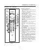
CONVECTION OVEN CONTROLS BLODGETT IQ2T VISION CONTROL COMPONENT DESCRIPTION 1 1. OVEN POWER SWITCH - controls power to the oven. 2. DISPLAY - displays temperature and other conĆ troller related information. 3. PROGRAM KEY - press to enter the programĆ ming mode. 2 4. PROGRAM ARROW KEYS - use to move through programming menus and options 4 3 5 6 5. HEAT LED - when lit indicates the control is callĆ ing for heat. 7 6. PROG LED - when lit indicates the controller is in the programming mode. 8 7.
OPERATION & CALIBRATION OVEN OPERATION Oven Startup: 1. Toggle the POWER SWITCH (1) to ON. The disĆ play gives the software revision level. The oven preheats to the lowest programmed first stage temperature. The LEDS (16) for all products with the same first stage temperature light. Single Product Cooking Procedure: NOTE: If the led next to the desired product key is lit skip step 1. 1. Press the desired PRODUCT KEY (17). The oven preheats to the first stage temperature for the seĆ lected product.
CONVECTION OVEN CONTROLS If the shelf timing function is toggled to the off position for that product, pressing the product key will start the cook cycle. The DISPLAY (2) scrolls the product name and counts down the remaining cook time. 3. Load the second product. Press the desired PRODUCT KEY (17). the DISPLAY (2) reads PICK SHLF Oven Cool Down: 1. Close the oven door. Press the COOL DOWN KEY (8). NOTE: Cool down cannot be activated with the oven door open.
OPERATION & CALIBRATION To select the product to program 2. Press the desired product key. The display reads: All Name With All highlighted, press the PROGRAM KEY (10). The display reads: Product Name AAA The first alphabetical listing in the product name library appears. 3. To change the product name, use the PROĆ GRAM ARROW KEYS (4) to scroll through the product name library. When the desired product name is highlighted, press the PROGRAM KEY (10) to select. To program the product 4.
CONVECTION OVEN CONTROLS Stage 1 Fan Cyc XXX Definition: If you would like the alarm to sound prior to the completion of the cook cycle you may program it here. The alarm time counts up from the beĆ ginning of the cook cycle. For example, if you want an alarm 9 minutes into the cook cycle, program the alarm time at 9:00. Definition: There are 3 options for fan cycle time: Pulse, Heat and Full. Pulse allows the fan to turn on and off as proĆ grammed. Heat allows the fan to operĆ ate with heat only.
OPERATION & CALIBRATION 12. Press the PROGRAM KEY (10). The display reads: Hold Time XX:XX Product Cnt Programming Use the PROGRAM ARROW KEYS (4) to scroll down until exit is highlighed. Press the PROĆ GRAM KEY (10) to exit the programming mode. Use the PRODUCT KEYS (17) to enter deĆ sired hold time. If a hold time of 00:00 is enĆ tered skip to step NO TAG. Press the PROĆ GRAM KEY (10). MANAGER LEVEL PROGRAMMING Entering the manager programming mode 1. Press and hold the PROGRAM KEY (10).
CONVECTION OVEN CONTROLS Tone Volume XXX Use the PROGRAM ARROW KEYS (4) to select None, 1, 2, 3 or 4. Press the PROGRAM KEY (10) to select the desired level for all audible signals. 4. The display reads: Temperature XXX Use the PROGRAM ARROW KEYS (4) to select either F or C. Press the PROGRAM KEY (10) to select the desired temperature units. 5. The display reads: Definition - Setback time is an energy savings feature that automatically lowĆ ers the cavity temperature when the oven is idle.
OPERATION & CALIBRATION Save Library ADD Definition - This function programs time for the oven to idle after reaching the preheat temperature allowing heat to saturate the oven cavity. The preheat time only applies to the initial preheat after a cold start. This is strictly a prompt, the user may begin a bake cycle even with the preheat prompt disĆ played. Use the PRODUCT KEYS (17) to enter a preheat time. Press the PROGRAM KEY (10).
CONVECTION OVEN CONTROLS To clear the alarm name, press the TEMP/ TOGGLE/CLEAR KEY (11). NOTE: Use product key 1 for spaces, periods, quotation marks and underlines. 5. Once the alarm name has been entered, press the PROGRAM KEY (10). The display reads: Save Library ADD SERVICE LEVEL PROGRAMMING Entering the SERVICE programming mode NOTE: All service programming options can be acĆ cessed using this program entry procedure. 1. Press and hold the PROGRAM KEY (10).
OPERATION & CALIBRATION Using the DIAGNOSTICS function Viewing and Resetting the PROGRAM RUN TIMES 1. Use the PROGRAM ARROW KEYS (4) to select Diagnostics. Press the PROGRAM KEY (10). 1. Use the PROGRAM ARROW KEYS (4) to select RuntImes. Press the PROGRAM KEY (10). 2. The display reads: 2. The display reads: Recovery Time 1 XX:XX Heat Cycles X Use the PROGRAM ARROW KEYS (4) to view the previous five recovery times. Press the PROĆ GRAM KEY (10). 3.
CONVECTION OVEN CONTROLS Use the PROGRAM ARROW KEYS (4) to scroll up until Exit is highlighted. Press the PROGRAM KEY (10). Reset All Counts XXX Use the PROGRAM ARROW KEYS (4) to togge select either Yes (to reset the counts) or No. Press the PROGRAM KEY (10) Exiting the SERVICE program mode NOTE: Use this exit procedure for all service proĆ gramming options. 1. The display reads: System Factory 1-58 2.
OPERATION & CALIBRATION HOW COOK AND HOLD WORKS With the optional COOK & HOLD feature, meat is roasted at lower temperatures for longer periods of time. This preserves flavor and tenderness and preĆ vents over drying. There are three phases in cook and hold roasting. 225_ 200_ Temperature (F) Cooking from Stored Heat - when the primary cook time expires, the oven automatically switches to HOLD. The product continues to cook from the heat stored in the oven.
CHAPTER 2 DECK OVEN CONTROLS 2-1
DECK OVEN CONTROLS 1200 SERIES CONTROL COMPONENT DESCRIPTION 1. TIMER - Used to set the desired cook time. 2. THERMOSTAT INDICATOR LIGHT - When lit inĆ dicates heaters are in operation. When the light goes out, the oven has reached set operating temperature. 1 3. OVEN THERMOSTAT - Controls the oven temĆ perature at desired settings. 2 4. UPPER HEATER SWITCH - Controls input to the upper heater. OFF = no input, LOW = 1/4 input, MED = 1/2 input, HIGH = full input. 5.
OPERATION & CALIBRATION 1400 SERIES - ELECTRO MECHANICAL THERMOSTAT & TIMER COMPONENT DESCRIPTION 1. POWER SWITCH - Controls the power to the oven. When switched to OVEN ON, the oven is operating in the normal heating mode. OVEN OFF, turns the oven off. 1 2. OVEN THERMOSTAT - Controls the oven temĆ perature at desired settings. 3. LIGHT OFF OVEN INDICATOR LIGHT - When lighted indicates heaters are in operation. When the light goes out, the oven has reached set opĆ erating temperature. 2 4.
DECK OVEN CONTROLS 1400 SERIES - SOLID STATE TEMPERATURE CONTROL COMPONENT DESCRIPTION 1. POWER SWITCH - Controls the power to the oven. When switched to OVEN ON, the oven is operating in the normal heating mode. OVEN OFF, turns the oven off. 1 2. DIGITAL DISPLAY - Displays the time, temperaĆ ture and controller related information. 3. TIME DIAL - A dial to set the cook time. 4. TEMPERATURE DIAL - A dial to set the cook temperature. 5. START TIMER - Starts the timing cycle.
OPERATION & CALIBRATION 900 SERIES CONTROL CONTROL DESCRIPTION 1. AUTOMATIC SAFETY PILOT VALVE - provides complete gas shutĆoff in the event of pilot failure. 2. MANUAL CONTROL VALVE - provides manual control of gas flow to the main burner through the thermostat. 3. THERMOSTAT - Provides regulation of oven temperature at setting selected by the oven opĆ erator. 1 OPERATION Lighting 1. Turn the MANUAL CONTROL VALVE (2) to OFF. 2. Push the red button on the AUTOMATIC SAFETY PILOT VALVE (1). 2 3.
DECK OVEN CONTROLS 1048 & 1060 SERIES CONTROL OPERATION The operation of the 1048 Series Oven is as simple as 1, 2, 3. - Lighting, Preheating and Loading. Lighting 1. Turn the MANUAL CONTROL VALVE (2) to OFF. 2. Push the red button on the AUTOMATIC SAFETY PILOT VALVE (1). 1 3. Apply a lighted match or taper to pilot burner. 4. After pilot burner lights, continue to depress red button for about 30 seconds and release. 2 5. Turn the MANUAL CONTROL VALVE (2) to ON. 6.
OPERATION & CALIBRATION 1048DD CONTROL 1. STEAM POWER SWITCH - Controls power to the steam generator. 8. STEAM LIGHT - Indicates that the steam soleĆ noid is open allowing steam to enter the unit. 2. TEMPERATURE KEY - Displays the current temperature. Used to toggle between the panel and the deck temperature. 9. DECK LIGHT - Illuminates when the temperaĆ ture on the display indicates the deck. 3. PANEL LIGHT - Illuminates when the temperaĆ ture on the display indicates the top panel. 4.
DECK OVEN CONTROLS PREHEAT CYCLE THE IDLE CONDITION NOTE: From a cold start it will take 2Ć3 hours to preĆ heat the deck. From the sleep mode it will take 1Ć2 hours to preheat the deck. The computer maintains the following temperatures when the oven is idle. 1. Toggle the power switch on the front of the steam generator to ON. NOTE: The generator fills for approximately three seconds after being turned on. DO NOT turn the generator on and off continĆ uously. This can cause the generator to overfill. 2.
OPERATION & CALIBRATION SLEEP MODE: The sleep mode is used to maintain a deck temperaĆ ture of approximately 200_F overnight. Using the sleep mode decreases the preheat time for the deck the following morning. Be sure the mechanically driven hood is left on. 1. Toggle the STEAM SWITCH (2) on the control panel to OFF. 2. Press and hold the SLEEP MODE KEY (3) for 2 seconds to enter the sleep mode. The display reads rEST.
CHAPTER 3 COMBI CONTROLS 3-1
COMBI CONTROLS STANDARD CONTROLS CONTROLS IDENTIFICATION 1. LOW WATER FILL LIGHT - during the fill cycle, this light remains on until the water in the steam generator is at the proper level and up to temperĆ ature. During normal operation the light should not be on. If the light comes on, check the water level in the steam generator. 2 1 3 2. DON'T STEAM LIGHT - indicates the unit is too hot to operate in the steam mode.
OPERATION & CALIBRATION OPERATION 1. Turn the MODE SELECTOR Switch (4) to the deĆ sired function. The POWER ON Light (3) illuminates. 2. Set the TIMER (5) for the desired cooking time or set it to STAY ON. The buzzer sounds and the unit shuts off when the time has expired. 3. For the HOT AIR and COMBI modes, set the TEMPERATURE Dial (2) to the desired cook temĆ perature. The HEATING INDICATOR Light (6) ilĆ luminates and stays lit until the desired temperaĆ ture is reached.
COMBI CONTROLS OPTIONAL COOK & HOLD CONTROLS IDENTIFICATION 1. LOW WATER FILL LIGHT - when lit indicates low water level in the steam generator. 1 2 2. DON'T STEAM LIGHT - when lit indicates the unit is too hot to operate in the steam mode. 3 3. POWER ON LIGHT - when lit indicates power to the unit is turned on. 4. MODE SELECTOR SWITCH - controls power to the oven and selection of steam, hot air and combi modes. The convection fan runs with the switch in steam, hot air, combi or cool down. 4 5.
OPERATION & CALIBRATION MANUAL OPERATION PROGRAMMED OPERATION 1. Turn the SELECTOR SWITCH (3) to the desired mode. The LED above the manual key lights. NOTE: See page 3-12 for programming instrucĆ tions. 2. Press the TEMPERATURE ARROW KEYS (8) to set the stage one cook temperature. 1. Turn the SELECTOR SWITCH (3) to the desired mode. 3. Press the TIME ARROW KEYS (5) to set the stage one cook time. 2. Press the desired PRODUCT KEY (12). The LED above the selected key lights. 4.
COMBI CONTROLS PROGRAMMING THE PRODUCT KEYS PROGRAMMING THE MANUAL KEY NOTE: Each product key can hold two programs: one for steam and one for hot air/combi. Hot air programs can be used in combi. NOTE: The manual key may be used for manual cooking and programmed for two products, one for steam and one for hot air/combi. Hot air programs can be used in combi. 1. Turn the SELECTOR SWITCH (3) to the desired mode. 2. Press the desired PRODUCT KEY (12). 3.
OPERATION & CALIBRATION BC14 STANDARD CONTROL CONTROLS IDENTIFICATION 1. MODE SELECTOR SWITCH - turns power to the oven on or off. Allows selection of Steam, Hot Air, Combi or Cool Down Modes. 2. TEMPERATURE DIAL - used to set desired cooking temperature. 9 3. STEAM INJECTION TIMER - used to set steam time 1 4. STEAM ON DEMAND SWITCH - used to initiĆ ate steam injection cycle 5. TIMER DIAL - used to set desired cook time. 6. FAN SPEED SWITCH - used to select low or high speed. 2 7.
COMBI CONTROLS OPERATION Steam on Demand 1. Turn the MODE SELECTOR Switch (1) to the deĆ sired function. Steam on Demand is helpful in many ways. The steam injection allows a much faster, consistent, even heat transfer. It also increases product moisture and reduces shrinkage while cooking faster and helps the oven temperature recover faster. Steam on Demand allows for Combi Frying oven ready breaded foods to perfection and crusty breads are a breeze. 2.
OPERATION & CALIBRATION BC14 OPTIONAL COOK & HOLD CONTROLS IDENTIFICATION 1. POWER ON LIGHT - when lit indicates power to the unit is turned on. 1 2. STEAM LAMP - illuminated when steam is beĆ ing added to cooking process 2 3. MODE SELECTOR SWITCH - controls power to the oven and selection of steam, hot air and combi modes. The convection fan runs with the switch in steam, hot air, combi or cool down. 3 4. TIME DISPLAY - gives cook time. 4 5.
COMBI CONTROLS 19. FAN SPEED SWITCH - used to select low or high speed. alarm. The control maintains the stage one cook temperature. 20. FLUSH/DRAIN SWITCH - used to flush/drain the steam generator for decalcification. 9. Turn the SELECTOR SWITCH (3) to OFF to shut down the oven/steamer. NOTE: BC14DS, the direct steam unit, does not have a flush/drain switch NOTE: Time and temperature settings may be changed at any time during manual operaĆ tion. Press the time arrow keys to change the cook time.
OPERATION & CALIBRATION STEAM ON DEMAND PROGRAMMING THE PRODUCT KEYS Steam on Demand is helpful in many ways. The steam injection allows a much faster, consistent, even heat transfer. It also increases product moisture and reduces shrinkage while cooking faster and helps the oven temperature recover faster. Steam on Demand allows for Combi Frying oven ready breaded foods to perfection and crusty breads are a breeze. NOTE: Each product key can hold two programs: one for steam and one for hot air/combi.
COMBI CONTROLS PROGRAMMING THE MANUAL KEY NOTE: The manual key may be used for manual cooking and programmed for two products, one for steam and one for hot air/combi. Hot air programs can be used in combi. 1. Turn the SELECTOR SWITCH (3) to the desired mode. 2. Press the MANUAL KEY (13). The LED above the manual key lights. 3. Press the TEMPERATURE ARROW KEYS (8) to set the stage one cook temperature. 4. Press the TIME ARROW KEYS (5) to set the stage one cook time. 5. Press the STAGE TWO KEY (11).
OPERATION & CALIBRATION BCS6 STANDARD CONTROLS CONTROLS IDENTIFICATION 1 1. LOW WATER FILL LIGHT - during the fill cycle, this light remains on until the water in the steam generator is at the proper level and up to temperĆ ature. During normal operation the light should not be on. If the light comes on, check the water level in the steam generator. 2 2. POWER ON LIGHT - Indicates the unit is in Steam mode. 3. MODE SELECTOR SWITCH - Turns power to the steamer on or off. Allows selection of steam mode.
COMBI CONTROLS BCS6 PUSH BUTTON POWER SAVER" CONTROL CONTROLS IDENTIFICATION 1 1. LOW WATER FILL LIGHT - during the fill cycle, this light remains on until the water in the steam generator is at the proper level and up to temperĆ ature. During normal operation the light should not be on. If the light comes on, check the water level in the steam generator. 2 2. POWER ON LIGHT - Indicates the unit is in Steam mode. 3. MODE SELECTOR SWITCH - Turns power to the steamer on or off.
OPERATION & CALIBRATION CNVĆ14 STANDARD CONTROLS CONTROLS IDENTIFICATION 1. POWER ON LIGHT - when lit indicates power to the unit is turned on. 1 2. SELECTOR SWITCH - allows selection of Hot Air or Cool Down Mode. 3. TEMPERATURE DIAL - used to set desired cooking temperature. 4. HEATING INDICATOR LIGHT - lights when the Hot Air heating is in operation. 2 5. TIMER DIAL - used to set desired cook time. 6. FAN SPEED SWITCH - used to select LOW or HIGH speed OPERATION 3 1.
COMBI CONTROLS CNVĆ14 OPTIONAL COOK & HOLD CONTROLS IDENTIFICATION 1. POWER ON LIGHT - when lit indicates power to the unit is turned on. 1 2. MODE SELECTOR SWITCH - controls power to the oven and selection of hot air and cool down modes. The convection fan runs with the switch in hot air or cool down. 3. TIME DISPLAY - gives cook time. 2 4. TIME ARROW KEYS - press to enter cook time from 00:00 to 99:59. 3 5. TEMPERATURE DISPLAY - gives cook temĆ perature. 5 6.
OPERATION & CALIBRATION MANUAL OPERATION PROGRAMMED OPERATION 1. Turn the SELECTOR SWITCH (2) to HOT AIR. The LED above the manual key lights. NOTE: See page 3-18 for programming instructions. 2. Press the TEMPERATURE ARROW KEYS (7) to set the stage one cook temperature. 3. Press the TIME ARROW KEYS (4) to set the stage one cook time. 4. Press the STAGE TWO KEY (10). NOTE: Stage two can be used for either a hold mode or a second cook temperature.
COMBI CONTROLS PROGRAMMING THE PRODUCT KEYS PROGRAMMING THE MANUAL KEY 1. Turn the SELECTOR SWITCH (2) to HOT AIR. NOTE: The manual key may be used for manual and programmed cooking. 2. Press the desired PRODUCT KEY (11). 3. Press and hold the PROGRAM KEY (15) for five seconds. The control beeps. The product key LED and STAGE ONE LED (8) light. 1. Turn the SELECTOR SWITCH (2) to HOT AIR. 2. Press the MANUAL KEY (12). The LED above the manual key lights. 4.
OPERATION & CALIBRATION OPTIONAL MEAT PROBE CONTROLS IDENTIFICATION 1. Set the MODE SELECTOR Switch to the desired function. 1. MEAT PROBE SWITCH 2. Turn the MEAT PROBE Switch (1) to ON. Controls power to the meat probe. 2. MEAT PROBE CONTROL Use to set the desired probe temperature. IndiĆ cates the actual temperature of the product 3. To set the desired core temperature press the blue SET BUTTON (4) on the MEAT PROBE CONTROL (2). Use the up arrow key (6) to increase the setpoint temperature.
COMBI CONTROLS SYNERGY OPTIONAL MEAT PROBE CONTROLS IDENTIFICATION 1. MEAT PROBE SWITCH - controls power to the meat probe. 1. Set the MODE SELECTOR Switch to the desired function. 2. Turn the MEAT PROBE Switch (1) to ON. 2. MEAT PROBE CONTROL - use to set the deĆ sired probe temperature. Indicates the actual temperature of the product 3. To set the desired core temperature press and hold the * BUTTON (4) on the MEAT PROBE CONTROL (2). 3. MEAT PROBE CONNECTOR - receptacle for the plug in meat probe.
CHAPTER 2 CONVEYOR OVEN CONTROLS 2-1
CONVEYOR OVEN CONTROLS U.E. TEMPERATURE CONTROLLER WITH OPEN LOOP DC DRIVE SYSTEM 1 2 3 4 5 ON 6 OFF HEAT ON OFF BLOWER COOK TIME ON OFF 7 TEMPERATURE CONVEYOR FIGURE 1 CONTROL DESCRIPTION 1. COOK TIME DISPLAY - Displays the belt speed. 2. CONVEYOR ADJUSTMENT KNOB - Turn to adĆ just the conveyor speed. 3. TEMPERATURE CONTROL KNOB - Turn to set cook temperature. 4. HEAT LIGHT - Indicates the control is calling for heat. 5. HEAT SWITCH - Controls power to the burner. 6.
OPERATION & CALIBRATION U.E. TEMPERATURE CONTROLLER WITH CLOSED LOOP DC DRIVE 1 2 3 4 5 ON 6 OFF HEAT ON OFF BLOWER COOK TIME ON OFF 7 TEMPERATURE CONVEYOR FIGURE 2 CONTROL DESCRIPTION 1. COOK TIME DISPLAY - Displays the belt speed. 2. CONVEYOR ADJUSTMENT KEYS - Press to adĆ just the conveyor speed. 3. TEMPERATURE CONTROL KNOB - Turn to set cook temperature. 4. HEAT LIGHT - Indicates the control is calling for heat. 5. HEAT SWITCH - Controls power to the burner. 6.
CONVEYOR OVEN CONTROLS ATHENA TEMPERATURE CONTROLLER WITH OPEN LOOP DC DRIVE 1 2 3 4 5 6 7 8 ON 9 OFF HEAT COOK TIME ON OFF 10 ACTUAL SETPOINT ON OFF BLOWER HEAT TEMPERATURE CONVEYOR FIGURE 3 CONTROL DESCRIPTION 1. COOK TIME DISPLAY - Gives the belt speed. 2. CONVEYOR ADJUSTMENT KNOB - Turn to adĆ just the conveyor speed. 3. ACTUAL TEMPERATURE KEY - Press to disĆ play the actual oven temperature. 4.
OPERATION & CALIBRATION ATHENA TEMPERATURE CONTROLLER WITH CLOSED LOOP DC DRIVE 1 2 3 4 5 6 7 8 ON COOK TIME ON OFF 10 9 OFF HEAT ACTUAL SETPOINT ON OFF BLOWER HEAT TEMPERATURE CONVEYOR FIGURE 4 4. Turn the HEAT SWITCH (8) to ON. CONTROL DESCRIPTION 1. COOK TIME DISPLAY - Gives the belt speed. 2. ACTUAL TEMPERATURE KEY - Press to disĆ play the actual oven temperature. 3. CONVEYOR ADJUSTMENT KEYS - Press to adĆ just the conveyor speed. 4.
CONVEYOR OVEN CONTROLS COMPUTER CONTROLLER 1 2 9 3 8 7 6 5 4 FIGURE 5 CONTROL DESCRIPTION 1. DIGITAL DISPLAY - Displays the time, temperaĆ ture and controller related information. 2. OVEN ON/OFF - Controls power to the oven. 3. NUMERIC KEYS - Used to enter numerical data in the programming mode. 4. CLEAR KEY - Used to clear the display if an erĆ ror is made in the programming mode. 5. SET TEMP KEY - Used to view or program the temperature setpoint. 6.
OPERATION & CALIBRATION CONTROL OPERATION PROGRAMMING PROCEDURES To turn the oven on: Programming the Cook Time: 1. Press and hold the ON/OFF key (2). The display reads OFF when the oven is idle. 2. The display flashes WAIT D LOW D SET D TIME. 3. The FAN and HEAT status lamps (9) light. The fans begin to run. The heat rises to the proĆ grammed temperature. The conveyor belt travĆ els at the programmed speed. 1. Press the PROGRAM/ENTER key (8). To view the cook time setting: 1. Press the TIME key (7).
CONVEYOR OVEN CONTROLS DISPLAY INFORMATION D WAIT D LOW - indicates that the present oven temperature is lower than the set point temperaĆ ture. When the oven reaches the set point temĆ perature the display changes to READY. D READY - indicates that the oven is ready to acĆ cept product. D SET D TEMP D mmss - indicates the current cook time setting. D HIGH D TIME - indicates that the temperature is well above the set point. This usually occurs when moving from a higher āto a lower temperaĆ ture.
OPERATION & CALIBRATION PLC MANUAL CONTROL MANUAL CONTROL DESCRIPTION 1. DIGITAL DISPLAY - two line display gives the time, temperature and other control related inforĆ mation. 2. OVEN ON/OFF (ON/STANDBY) - controls powĆ er to the oven. 3. TEMPERATURE KEY - press to change the cook temperature. 4. ARROW KEYS - press to change the set time and temperature in the display. WARNING!! This oven, supplied with remote control, is equipped with an emergency shut down switch.
CONVEYOR OVEN CONTROLS OPERATION NOTE: The following example is in _F. The display will read _C if programmed in celsius. To turn the oven on: 1. Press the OVEN ON/OFF key (2). The control deĆ faults to the last time and temperature settings used. The display reads: SET TEMP XXXF HEAT COOK TIME XX:XX NOTE: HEAT appears in the top line of the display whenever the control calls for heat. 2. The fans begin to run. The conveyor belt begins to travel at the set cook time.
OPERATION & CALIBRATION PLC PROGRAMMABLE CONTROL MENU CONTROL DESCRIPTION 1. DIGITAL DISPLAY - two line display gives the time, temperature and other control related inforĆ mation. WARNING!! This oven, supplied with remote control, is equipped with an emergency shut down switch. Should you need to stop the belt, fans, or heat press the emergency switch. 2. OVEN ON/OFF (ON/STANDBY) - controls powĆ er to the oven. 3. ARROW KEYS - press to change the time and temperature in the display.
CONVEYOR OVEN CONTROLS MENU PROGRAMMING NOTE: The following example is in _F. The display will read _C if programmed in celsius. To enter programming mode: 1. With the oven off, press and hold the UP ARROW key (3) and the ENTER/RESET key (5) simultaĆ neously for approximately three seconds. The display reads: ACCESS CODE 000 3. Press the ENTER/RESET key (5) to enter the proĆ gramming mode.